TP-6735 7/17 67Section 5 Component Testing and Adjustment
Voltage and Frequency Adjustments Using
SiteTech
When the voltage and frequency adjustment
procedures require adjusting a voltage or speed
parameter, use the SiteTech parameters shown in
Figure 5-12 to adjust voltage and gain, or engine speed
and gain as necessary.
SiteTech Group Parameter
Engine Speed Governor Engine Speed Adjustment
Engine Speed Gain Adjustment
Voltage Regulator Average Voltage Adjustment
Volts per Hertz Slope
Volts per Hertz Cut-in
Frequency
Voltage Regulator Gain
Figure 5-12 Adjustments Using SiteTech Software
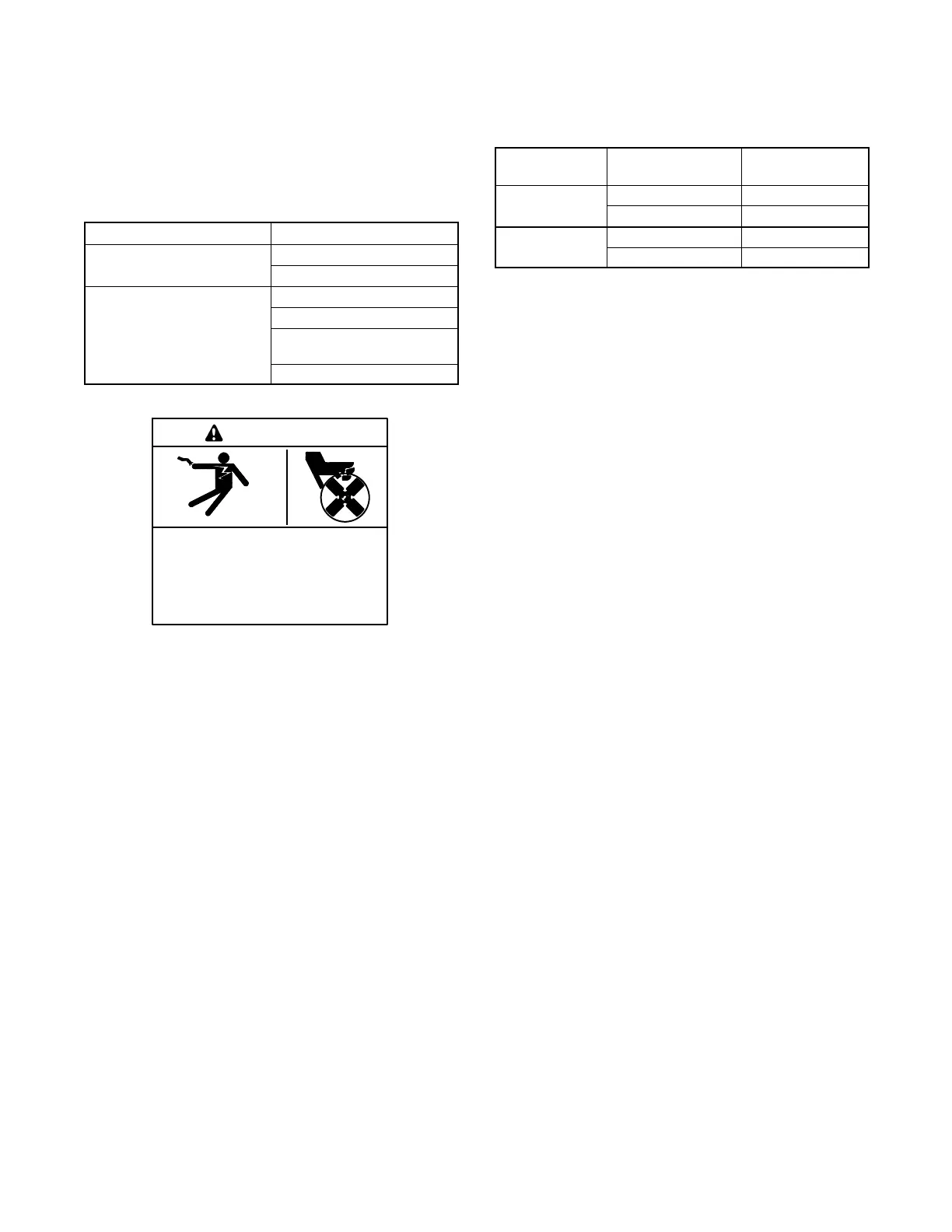
Hazardous voltage. Moving parts.
Will cause severe injury or death.
Operate the generator set only when
all guards and electrical enclosures
areinplace.
DANGER
Short circuits. Hazardous voltage/current will cause
severe injury or death. Short circuits can cause bodily injury
and/or equipment damage. Do not contact electrical
connections with tools or jewelry while making adjustments or
repairs. Remove all jewelry before servicing the equipment.
Grounding electrical equipment. Hazardous voltage will
cause severe injury or death. Electrocution is possible
whenever electricity is present. Ensure you comply with all
applicable codes and standards. Electrically ground the
generator set, transfer switch, and related equipment and
electrical circuits. Turn off the main circuit breakers of all
power sources before servicing the equipment. Never contact
electrical leads or appliances when standing in water or on wet
ground because these conditions increase the risk of
electrocution.
5.8.1 Voltage Adjustment Procedure
Refer to Figure 5-15 during the adjustment procedure.
1. Connect a digital voltmeter to measure output
voltage across L1 or L2 and L0. Set the meter to
measure AC v olts.
2. Start the generator set.
3. Follow the controller instructions in Figure 5-15 to
enter the adjustment mode. Increase or decrease
voltage (parameter 1P) until the output reaches the
desired voltage. See Figure 5-13.
Models
Voltage
Measurement
Approximate
Voltage, VAC
1 phase, 60 Hz
L--L0 120
L-L 240
1 phase, 50 Hz
L--L0 115
L-L 230
Figure 5-13 Voltage Measurement
4. Follow the controller instructions to step to the
voltage gain (parameter 2P) adjustment menu.
Adjust the voltage gain (2P) until the light flicker
minimizes. Save the settings. See Figure 5-15.
5. Check and readjust the voltage if necessary.
6. Save the settings. Refer to Figure 5-15 for
instructions.
Note: The controller w ill revert to the previous
settings at the next startup if the changes
are not saved.
7. Stop the generator set.
5.8.2 Volts per Hertz (Hz) Adjustments
(Droop)
The volts per hertz (droop) setting can only be adjusted
using a personal computer running Kohlerr SiteTecht
software. Follow the instructions in this section and
refer to TP-6701, SiteTech Software Operation Manual,
to adjust the Voltage Regulator Volts per Hertz Slope
parameter.
When the frequency falls below the cut-in frequency
(see Figure 5-14), output voltage is reduced to relieve
the engine. The magnitude of the voltage reduction is
set by the voltage regulator volts per hertz slope. To
determine whether droop adjustment is required,
monitor engine speed and output voltage as loads are
applied, and watch for the following conditions.
D If there is excessive droop in engine speed and little
droop in voltage, increase the volts per hertz value.
D If there is little engine speed droop but excessive
voltage droop, decrease the volts per hertz value.

 Loading...


