TP-5393 9/93 Wiring Diagrams 5-3
4 3 2 1
1
2
4
5
6
7
8
9
3
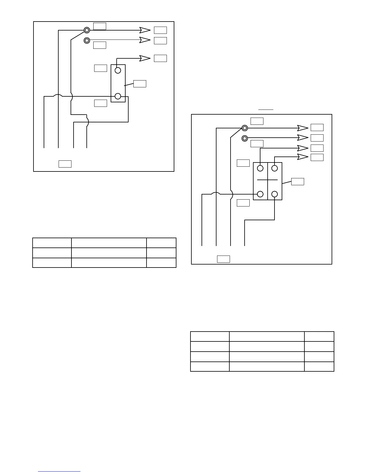
1. L0 (Neutral)
2. Ground
3. L0
4. Ground
5. L1
6. 1-Pole Circuit Breaker
7. Stator Leads
8. Line Side
9. Load Side
Figure 5-2. View B—120 Volt, 2 Wire
60 Hz 50 Hz
L0-L1 120 Volt 110 Volt
L0-L2 120 Volt 110 Volt
120/240-Volt (or 110/220-Volt)
Configurations—Figure 5-3 (View C)
Jumper lead not used. If unit was originally wired for
straight120volt(or110volt),3wire,besurejumperlead
isremoved(seeFigure 5-1forlocation). Circuitbreaker
MUSTbeacircuitbreakermanufacturertwo-polecircuit
breaker. Two single-pole circuit breakers do not
conform to NEC requirements when supplying a 240
volt (or 220 volt) load. This is true even if they are
mechanically attached together. Leads L1 and L2 are
differentphasesandmustneverbeconnectedtogether.
4 3 2 1
1
2
3
4
5
6
7
8
9
10
1. L0 (Neutral)
2. Ground
3. L0
4. Ground
5. L2
6. L1
7. Factory Two-Pole Circuit Breaker
8. Stator Leads
9. Line Side
10. Load Side
Figure 5-3. View C—120/240 Volt, 3 Wire
60 Hz 50 Hz
L0-L1 120 Volt 110 Volt
L0-L2 120 Volt 110 Volt
L1-L2 240 Volt 220 Volt
 Loading...


