5-2 Wiring Diagrams TP-5393 9/93
Four-Lead Reconnectable
(Single-Phase) Generator Sets
Where Generator Output Can Be
Reconnected For 120 Volt or
120/240 Volt, 60 Hz; or
110 Volt or 110/220 Volt, 50 Hz
To illustrate theproper reconnection of 4-leadgenerator
sets, the following information is provided. In all cases,
the National Electrical Code (NEC) should be followed.
NOTE
When a generator set is reconnected to a voltage
different than nameplate voltage, notice should be
placed on the unit indicating this change. A decal (part
no.246242)isavailableforthispurposefromauthorized
Kohler dealers.
120-Volt (or 110-Volt)
Configurations—Figure 5-1 and
Figure 5-2 (Views A and B)
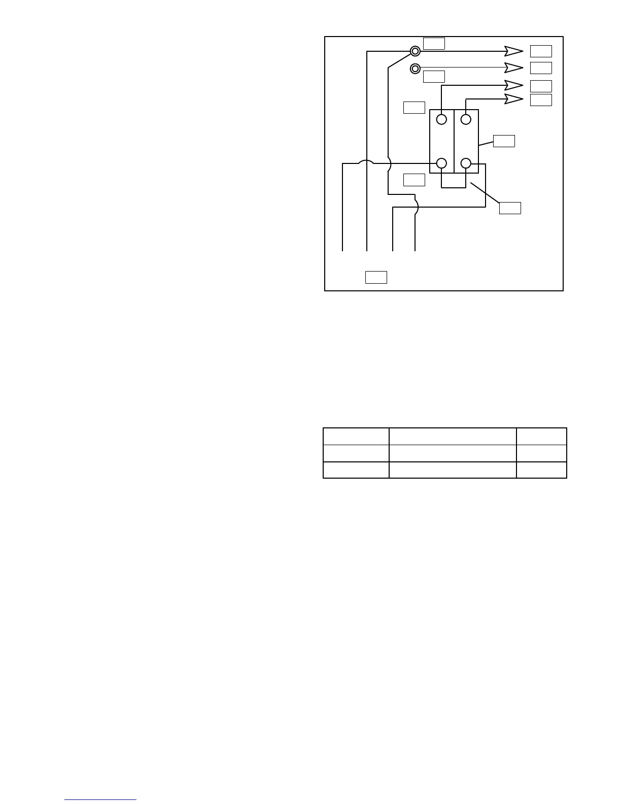
The load-side terminals of the circuit breaker are not to
be connected together when a factory two-pole circuit
breaker is used, see Figure 5-1. If the installation
requires a 120 volt, 2-wire system, a single-pole circuit
breaker must be used. See Figure 5-2. When
connecting stator phase leads together, the output lead
(L1) must besized accordingly. It is recommended that
a jumper lead be used on the line side of the circuit
breaker. This allows for balancing of the load of the
generator set.
4 3 2 1
1
2
3
4
5
6
7
8
9
10
11
1. L0 (Neutral)
2. Ground
3. L0
4. Ground
5. L1
6. L2
7. Factory Two-Pole or (2) 1-Pole Circuit Breakers
8. Jumper Lead
9. Stator Leads
10. Line Side
11. Load Side
Figure 5-1. View A—120 Volt, 3 Wire
60 Hz 50 Hz
L0-L1 120 Volt 110 Volt
L0-L2 120 Volt 110 Volt
 Loading...


