TP-6053 7/04 13Section 4 Fuel System
Section 4 Fuel System
4.1 General
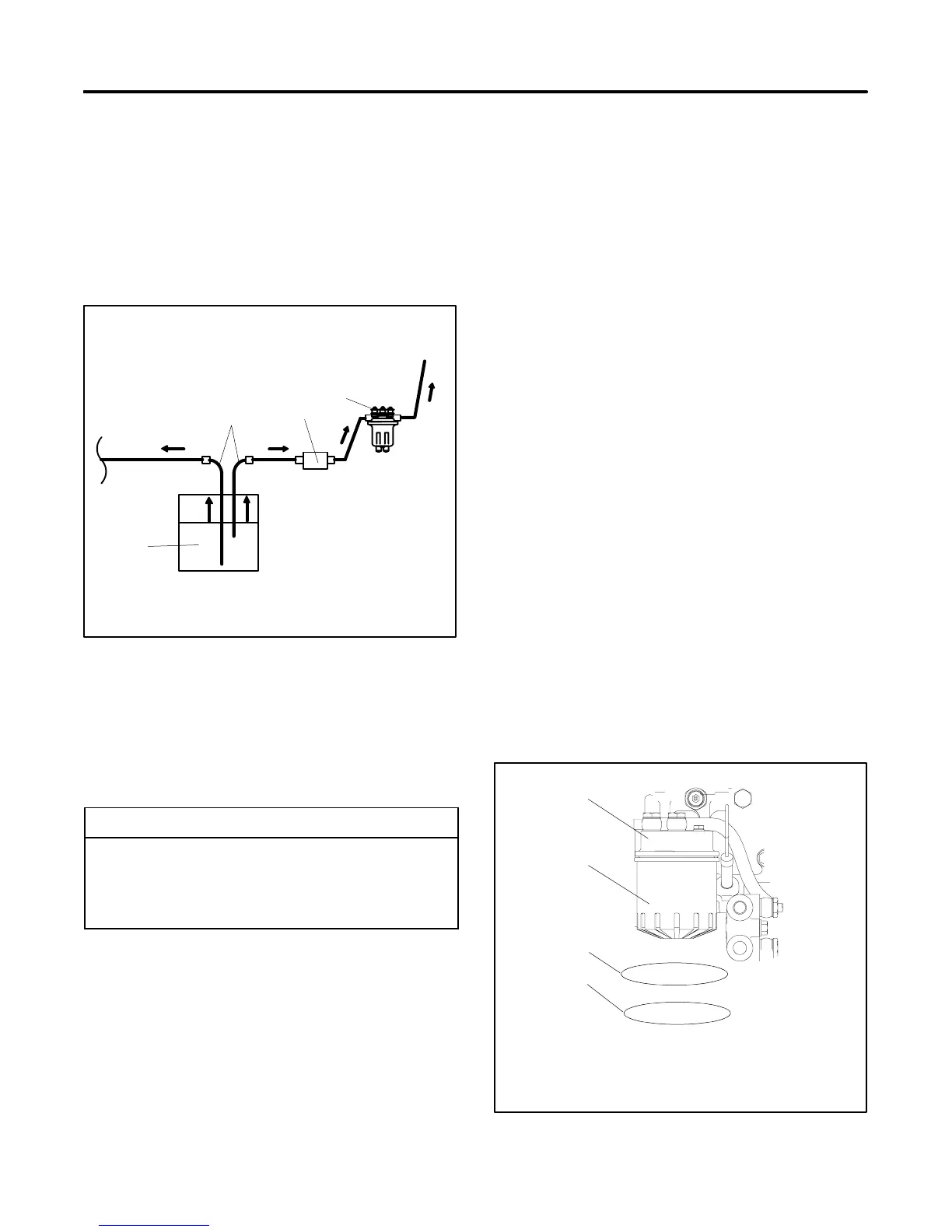
In most installations, both the generator set and the
propulsion engine operate from a common fuel tank with
a dual dip tube arrangement. The generator set dip tube
is shorter than the propulsion engine’s dip tube. With
this arrangement, fuel may not be available to the
generator set when the fuel supply is low. See
Figure 4-1 for a fuel system schematic.
Generator
Set
Propulsion
Engine
1
2
4
3
To fuel
pump
1. Fuel tank
2. Dual dip tubes
3. Fuel filter
4. Fuel feed pump
Figure 4-1 Fuel System Schematic Typical
4.2 Fuel Specifications
Use a clean, good quality diesel fuel oil with a cetane
number of 45 or greater. Clean fuel prevents diesel fuel
injectors and pumps from clogging.
Fuel Recommendation
United States
ISO 8217 DMA, BS 2869 Part 1 Class
A1 or Part 2 Class A2
United Kingdom BS 2869-1983, Part 2 Class A2
Germany DIN 51 601-1978
4.3 Fuel Filter
The quality and condition of the fuel largely determine
the filter’s useful life. Replace the fuel filter element
according to the service schedule. Section 1.2 shows
the location of the fuel filter. There are two types of fuel
filtering systems, the spin-on fuel filter and the fuel filter
element. Use the applicable procedure below to replace
the fuel filter. See Figure 4-2 or Figure 4-3.
Spin-On Fuel Filter Replacement Procedure
1. Place the generator set start/stop switch in the
STOP position.
2. Disconnect the generator set engine starting
battery, negative (--) lead first.
3. Close the fuel supply valve.
4. Remove the fuel filter. See Figure 4-2.
5. Clean the contact surface of the fuel filter adapter.
6. Lightly lubricate the gasket surface of the new fuel
filter with fresh fuel. Thread the filter onto the
adapter until the gasket makes contact;
hand-tighten the filter an additional one-half turn.
7. Open the fuel supply valve.
8. Reconnect the generator set engine starting
battery, negative (--) lead last.
9. Bleed the fuel system. See Section 4.4.
1
TP-606111
1. Fuel filter adapter
2. Fuel filter
3. Removal (counterclockwise)
4. Installation (clockwise)
<
<
<
<
2
3
4
Figure 4-2 Spin-On Fuel Oil Filter
 Loading...