TP-6053 7/04 51Section 10 Voltage Reconnection and Wiring Diagrams
Section 10 Voltage Reconnection and Wiring Diagrams
10.1 Voltage Reconnection
The following information illustrates the proper
reconnection of 4-lead generator sets. In all cases,
follow the National Electrical Code (NEC).
NOTICE
Voltage reconnection. Affix a notice to the generator set after
reconnecting the set to a voltage different from the voltage on
the nameplate. Order voltage reconnection decal 246242
from an authorized service distributor/dealer.
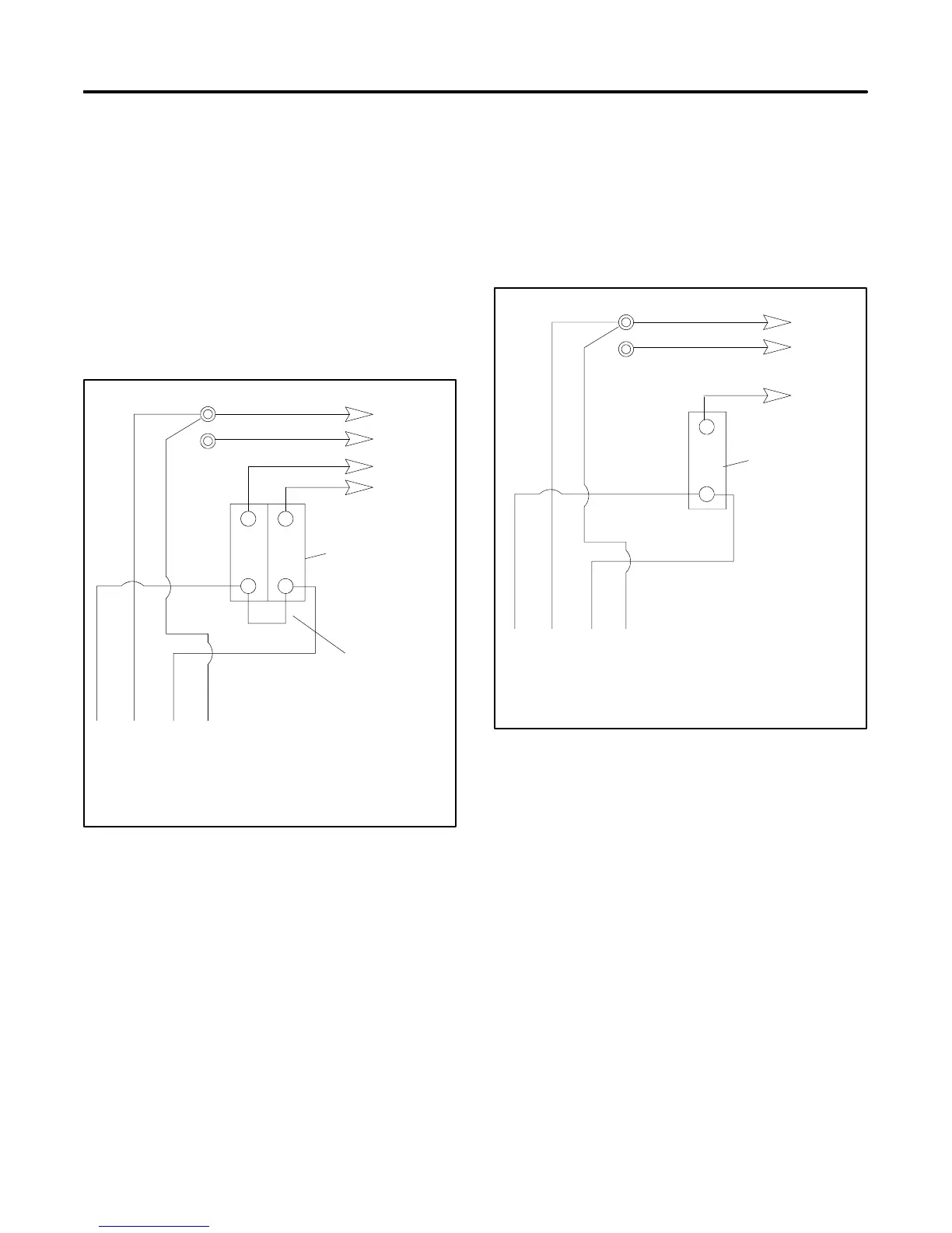
10.1.1 100--120-Volt Configurations
4321
Stator Leads
LO
GRD
LO (Neutral)
Ground
Load
Side
Line
Side
Factory
2-Pole
or (2) 1-Pole
Circuit Breakers
Jumper
Lead
L1
L2
100--120 Volt, 3 Wire
60 Hz 50 Hz
L0--L1 100--120 Volt 100--120 Volt
L0--L2 100--120 Volt 100--120 Volt
Figure 10-1 100--120 Volt, 3 Wire
Do not connect the load-side terminals of the circuit
breaker together when using a factory 2-pole circuit
breaker. See Figure 10-1. If the installation requires a
100--120-volt, 2-wire system, use a 1-pole circuit
breaker. See Figure 10-2. When connecting stator
phase leads together, size the output lead (L1)
accordingly. Use a jumper lead on the line side of the
circuit breaker to balance the generator set load.
60 Hz 50 Hz
L0--L1 100--120 Volt 100--120 Volt
L0--L2 100--120 Volt 100--120 Volt
4321
Stator Leads
LO
GRD
LO (Neutral)
Ground
Load
Side
Line
Side
1-Pole
Circuit
Breaker
L1
100--120 Volt, 2 Wire
Figure 10-2 100--120 Volt, 2 Wire
 Loading...