TP-6053 7/0452 Section 10 Voltage Reconnection and Wiring Diagrams
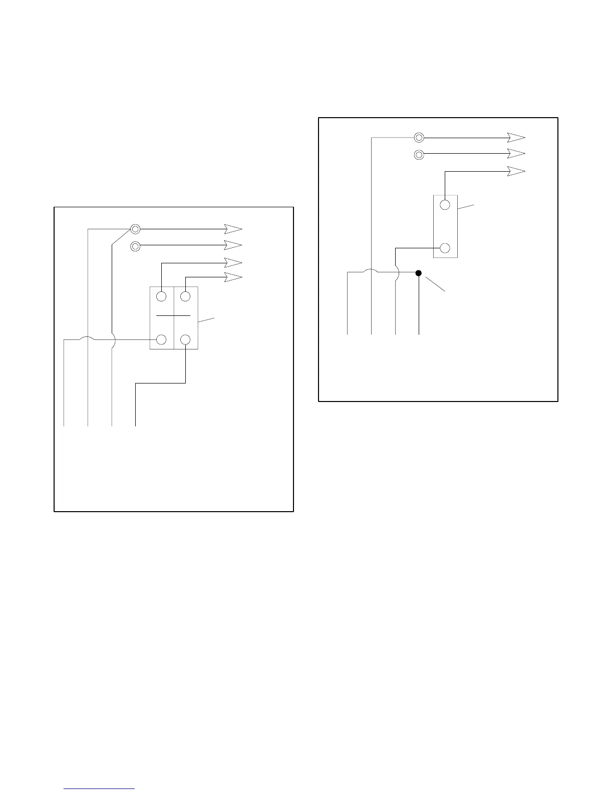
10.1.2 100--120/200--240 -Volt
Configurations
This configuration does not use a jumper lead. If the unit
was originally wired for straight 100--120 volt, 3 wire,
remove the jumper lead (see Figure 10-1 and
Figure 10-2 for location). Select a circuit breaker
manufactured with a 2-pole circuit breaker. Two 1-pole
circuit breakers do not conform to NEC requirements
when supplying a 200--240-volt load. This is true even if
they are mechanically attached together. Since leads
L1 and L2 are different phases, never connect them
together.
60 Hz 50 Hz
L0--L1 100--120 Volt 100--120 Volt
L0--L2 100--120 Volt 100--120 Volt
L1--L2 200--240 Volt 200--240 Volt
4321
Stator Leads
LO (Neutral)
Line
Side
Factory
2-Pole
Circuit
Breaker
Ground
Load
Side
100--120/200--240 Volt, 3 Wire
LO
GRD
L2
L1
Figure 10-3 100--120/200--240 Volt, 3 Wire
10.1.3 200--240-Volt Configurations
This configuration does not use a jumper lead. If the unit
was originally wired for straight 100--200 volt, 3 wire,
remove the jumper lead (see Figure 10-1 and
Figure 10-2 for location).
60 Hz 50 Hz
L0--L1 not used 200--240 Volt
4321
Stator Leads
LO
GRD
L1
LO (Neutral)
Line
Side
1-Pole
Circuit
Breaker
Ground
Load
Side
200--220--240 Volt, 2 Wire
Tape to insulate
from ground
Figure 10-4 200--240 Volt, 2 Wire
 Loading...