TP-6053 7/04 47Section 9 Generator Disassembly/Reassembly
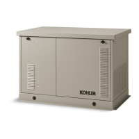
19. Install a sling on the stator housing. See
Figure 9-6.
20. Use a two-jaw puller to pull the end bracket/stator
assembly from the bearing on the rotor shaft. See
Figure 9-6.
21. Remove the s tator assembly from the rotor.
Remove or rotate the fan guard, if necessary, to
clear the vibromounts.
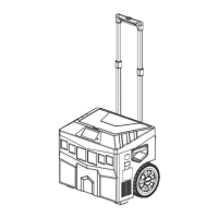
22. Remove the four locknuts and remove the fan and
fan spacer. See Figure 9-7.
23. Remove the six metric bolts to remove the drive
disc/rotor assembly from the engine flywheel. See
Figure 9-7.
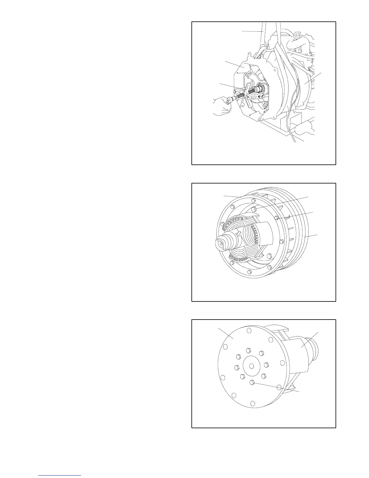
24. Clamp the rotor in a soft-jaw vise. Remove the eight
bolts and remove the drive disc assembly from the
rotor. SeeFigure9-8.
9.2 Reassembly
1. Clamp the rotor in a soft-jaw vise. Install the drive
disc on the rotor with disc studs facing the rotor.
Tighten the eight bolts to 40 Nm (30 ft. lbs.). See
Figure 9-8.
2. Install the rotor/drive disc assembly on the engine
flywheel using six washers and bolts. Tighten the
bolts to 27 Nm (20 ft. lbs.).
3. Install the fan to the drive disc using four spacers,
washers, and locknuts.
Note: Install the fan with the flange side facing
away from the flywheel. Space the studs so
that they allow the fan installation in one
position only.
558867
1
1. Sling
2. Fan guard
3. Two-jaw puller
4. End bracket
4
2
3
Figure 9-6 Stator Assembly Removal
558868
1
3
1. Fan
2. Bolt
3. Locknut
4. Rotor assembly
2
4
Figure 9-7 Disc/Rotor and Fan Assembly
5588610
1
2
3
1. Drive disc
2. Rotor
3. Bolt
Figure 9-8 Drive Disc
 Loading...