TP-6053 7/0438 Section 7 Generator Troubleshooting
7.7 Rectifier Module
The rectifier module, located between the exciter
armature and the main field, converts the AC from the
exciter armature to DC which magnetizes the generator
main field. Test the rectifier module as described in the
following steps.
Rectifier Module Test Procedure
1. Disconnect the exciter armature and the main field
leads from the rectifier module.
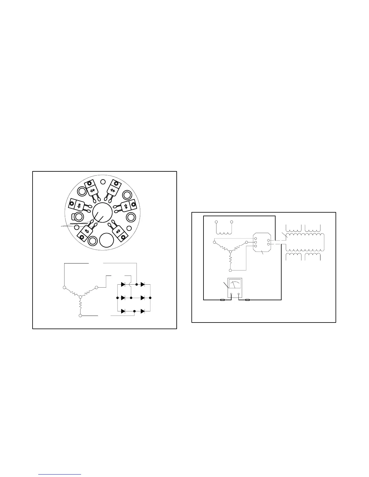
2. Use an ohmmeter on the R x 100 scale to check the
resistance between the rectifier diodes as shown in
Figure 7-10. The ohmmeter should show
resistance in one direction and, upon reversing the
ohmmeter leads, a high resistance in the other
direction. Replace the rectifier module if any of the
diodes tests differently than described.
A1
(AC)
(AC)
(AC)
C1
B1
A
B
C
+--
A
B
C
--
+
5588710
1
1. Diode terminal
Figure 7-10 Testing Rectifier Module
7.8 Rotor
The generator rotor (magnetized by DC current from the
rectifier module) rotating within the stator windings
induces AC voltage in the stator windings. Test the
generator rotor (main field) as described in the following
steps.
Rotor Test Procedure
1. Disassemble the generator.
2. Disconnect the generator main field windings from
rectifier module terminals F+ and F--.
3. Check the main field resistance by connecting an
ohmmeter across the main field F+ and F-- leads.
See Figure 7-11. The resistance reading for a cold
main field should be approximately 2.5--4.5 ohms.
A low reading indicates an internal short and a high
reading indicates an open winding. Replace the
main field if the ohmmeter readings indicate that
the main field is inoperative.
4. Perform a megohmmeter test on the main field as
described in the next step.
F+
F--
AC
AC
AC
5588711
1
2
3
4
5
6
1. Main field (rotor)
2. Stator windings
3. Rectifier module
4. Ohmmeter
5. Armature
6. Exciter field
Figure 7-11 Ohmmeter Connections on
Main Field
 Loading...