EasyManuals Logo
Home>Kohler>Controller>APM402

Kohler APM402 User Manual

Kohler APM402
172 pages
To Next Page IconTo Next Page
To Previous Page IconTo Previous Page
Page #149 background imageLoading...
Page #149 background image
TP-6694 9/20 149
6.2 Accessory Connections
The controller contains a circuit board equipped with terminal strip(s) for use in connecting external optional accessories
including alarms, battery chargers, and remote switches. The optional I/O board provides an additional two analog or digital
inputs and five digital outputs.
For specific information on accessory connections, refer to the accessory wiring diagrams in the wiring diagram manual and the
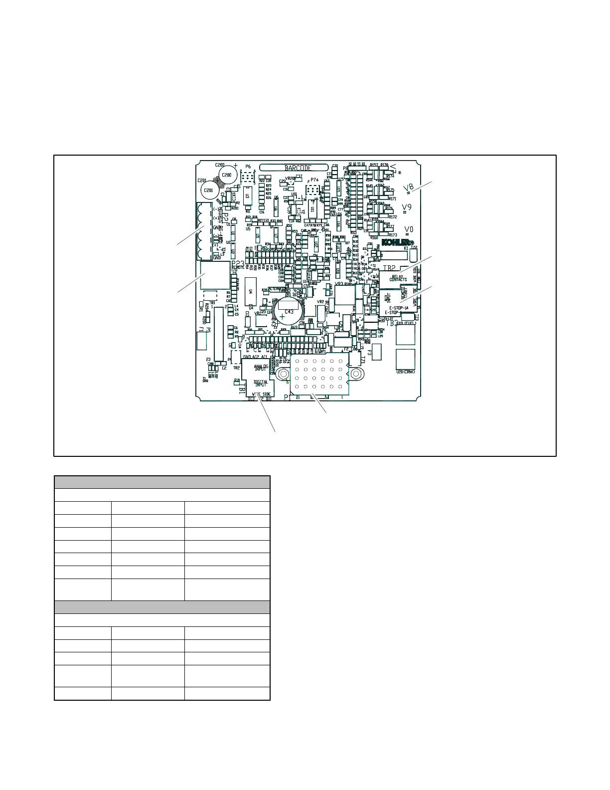
instruction sheet accompanying the kit. See Figure 87, Figure 88, and Figure 90 for controller circuit board connections.
Figure 87 Controller Circuit Board Connections
TB1 Terminal Strip
Analog and Digital Input Connections
Terminal
Description
Connection
TB1-DI 1
DCH1
No Function
TB1-DI 2
DCH2
Aux. Warning Switch
TB1-DI 3
DCH3
(see Note below)
TB1-AI 1
ACH1
No Function
TB1-AI 2
ACH2
No Function
TB1-GND
Ground
Common A/D
Ground
TB2 Terminal Strip
KI Relay Outputs
Terminal
Description
Connection
TB2-COM
Common
User- Defined
TB2-COM
Common
Common Fault (2)
TB2-NO
Normally Open
Common Fault
(32A)
TB2-NC
Normally Closed
User- Defined
P23 8-pin connector (RJ45)
(4) push-on terminal connectors
GM102396
P21 6-pin connector
TB1 6-position terminal block
P1 24-pin connector
TB2 4-position terminal block
TB3 6-position terminal block

Table of Contents

Questions and Answers:

Question and Answer IconNeed help?

Do you have a question about the Kohler APM402 and is the answer not in the manual?

Kohler APM402 Specifications

General IconGeneral
BrandKohler
ModelAPM402
CategoryController
LanguageEnglish

Related product manuals