TP-6694 9/20 33
1.2.8 Communication Ports
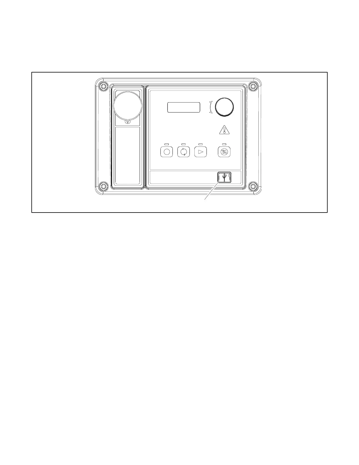
The main logic circuit board contains a single mini USB communication port for PC connections, see Figure 7. For Modbus
®
communication using RS-485, see the figure titled: Main Circuit Board Connectors (P21). Refer to the List of Related Materials
in the Introduction for corresponding SiteTech™ software and/or communication installation information.
Figure 7 Communication Port
1.2.9 Fuses
AC Circuit Fuses (TB5). Fuses are located inside the generator set control box. See Figure 8.
1.5-Amp (V7) fuse protects L1 sensing input to interconnection circuit board.
1.5-Amp (V8) fuse protects L2 sensing input to interconnection circuit board.
1.5-Amp (V9) fuse protects L3 sensing input to interconnection circuit board.
DC Circuit Fuses are located on the controller circuit board. See Figure 9.
1-Amp (F1) auto-resettable, fuse protects the controller circuits.
1-Amp (F2) auto-resettable fuse protects the controller circuits.
12-Amp (F3) non-replaceable fuse protects the engine/starting circuitry and accessories.

 Loading...


