TP-6694 9/20 31
1.2.6 Main Logic Circuit Board
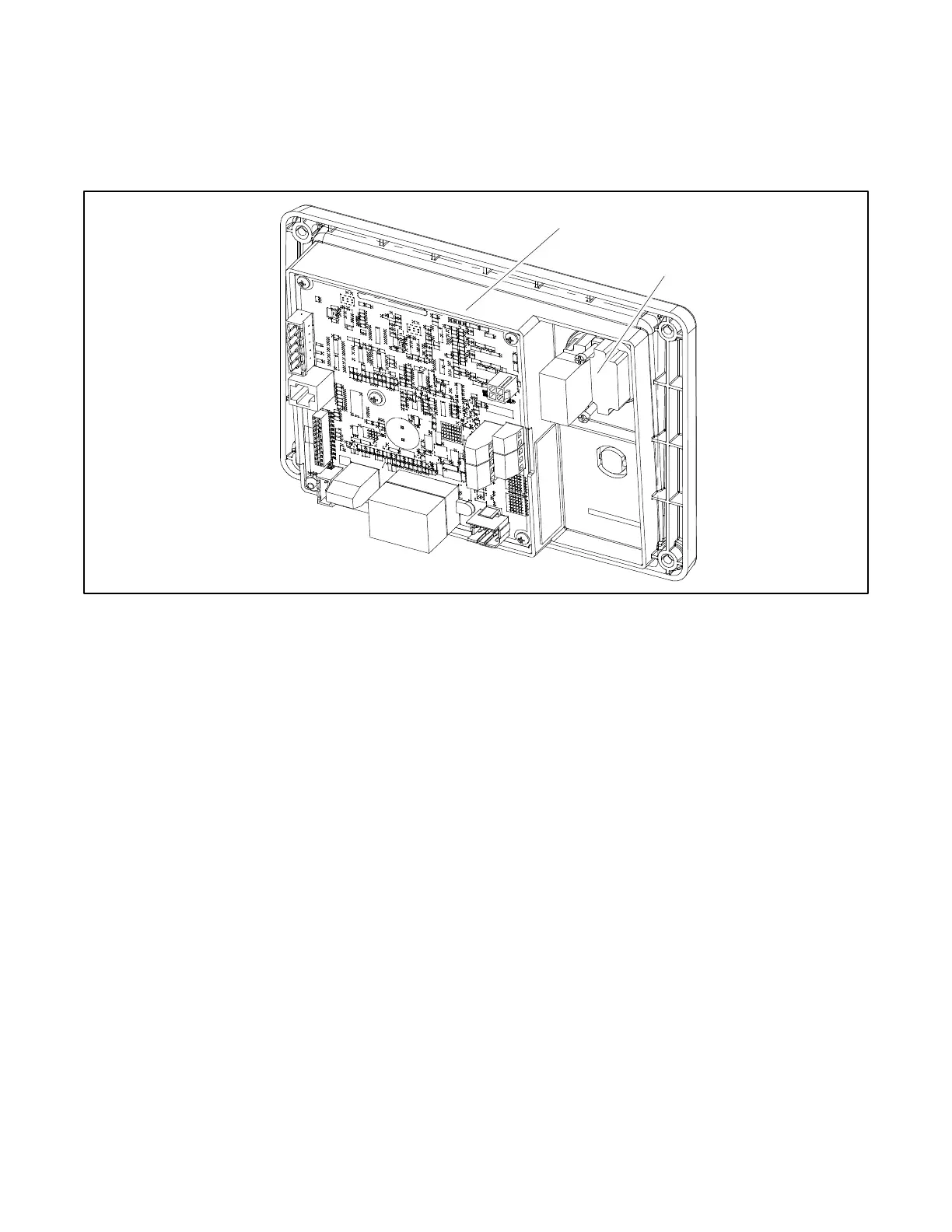
The main logic circuit board provides the terminal strips and connection sockets to connect the controller to the engine/generator,
input/output connections, optional I/O module kit, and circuit protection fuses. See Figure 5 and Figure 6 for the circuit board
connections. See the section titled: Accessories for more information.
Figure 5 Main Circuit Board and Emergency Stop Switch
Circuit Board Connections
P1 (24-Pin) Connector for engine/generator wiring harness.
(4) Push-on Connectors for V7/V8/V9/V0 for generator set output voltage connection.

 Loading...


