Fuel System and Governor
2162 690 01 Rev. C KohlerEngines.com
Typical carbureted fuel system and related components include following:
● Fuel Tank and Valve ● In-line Fuel Filter ● Carburetor
● Fuel Lines ● Fuel Pump
Fuel from tank is moved through in-line fi lter and fuel lines by fuel pump. Fuel then enters carburetor fl oat bowl and is
drawn into carburetor body and mixed with air. This fuel-air mixture is then burned in engine combustion chamber.
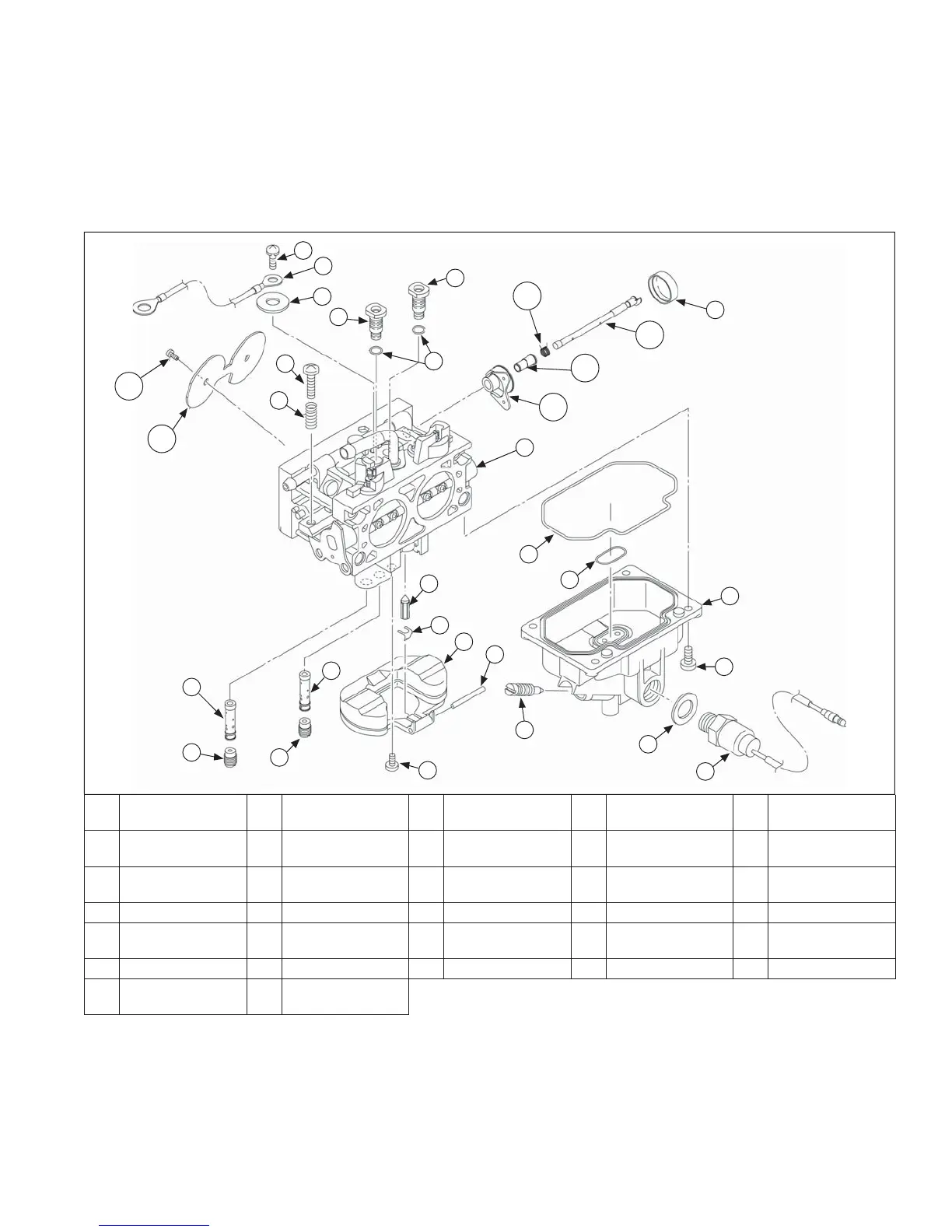
Keihin BK Two-Barrel Carburetor - Exploded View
A
Carburetor Body
Subassembly
B
Idle Speed
Screw
C
Idle Speed
Spring
D Screw E Ground Lead
F
Retaining
Washer
G
Slow Jet -
RH Side
H
Slow Jet -
LH Side
I
O-ring
(Slow Jet) (2)
J Fuel Bowl
K
O-ring (Fuel
Bowl - Upper)
L
O-ring (Fuel
Bowl Lower)
M Drain Screw N Bowl Screw (4) O Fuel Solenoid
P Sealing Washer Q Float R Pin S Screw T Float Clip
U
Float Valve/
Inlet Needle
V
Main Nozzle -
Right Side
W
Main Nozzle -
Left Side
X
Main Jet -
Right Side
Y
Main Jet -
Left Side
Z Choke Dust Cap AA Choke Shaft AB Spring AC Bushing AD Choke Lever
AE Choke Plate AF
Choke Plate
Screw (2)
D
E
F
G
H
I
C
B
Z
J
N
P
O
M
S
T
Q
R
U
K
L
V
X
W
Y
A
AF
AE
AA
AB
AC
AD
 Loading...