60
Reassembly
KohlerEngines.com 62 690 01 Rev. C
Valve Stem Seals
These engines use valve stem seals on intake and
exhaust valves. Always use new seals whenever valves
are removed from cylinder head. Seals should also be
replaced if worn or damaged. Never reuse an old seal.
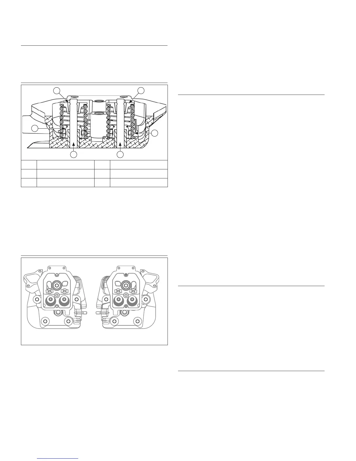
Assemble Cylinder Heads
C
D
BA
E
F
A Exhaust Valve B Intake Valve
C Spring D Retainer
E Keepers F Valve Stem Seals
Prior to installation, lubricate all components with engine
oil, paying particular attention to lip of valve stem seal,
valve stems, and valve guides. Install following items in
order listed below using a valve spring compressor.
● Intake and exhaust valves
● Valve spring retainers
● Valve springs
● Valve spring keepers
● Valve stem seals
Install Cylinder Heads
No. 1
No. 2
1
3
4
5
2
13
4
5
2
NOTE: Match numbers embossed on cylinder heads
and crankcase.
1. Check to make sure there are no nicks or burrs on
sealing surfaces of cylinder head or crankcase.
2. Check dowel pins are in place in two lower locations,
and install a new cylinder head gasket,
(printed side up).
3. Install cylinder head. Make sure head is fl at on
gasket and dowel pins. Install a fl at washer on
screws in locations 1 and 3. Install spacer followed
by a fl at washer on screw in location 5. See Figures
10-48 and 10-50. Start fi ve hex fl ange screws.
4. Tighten hex fl ange screws in two stages following
sequence shown to torque specifi cation.
5. Repeat procedure for opposite cylinder.
6. Make sure threads of pipe plugs for cylinder heads
are clean and dry. Install a plug into each cylinder
head above No. 2 screw location and tighten to
torque specifi cation.
Install Push Rods and Rocker Arms
NOTE: Push rods should always be installed in same
position as before disassembly.
1. Note mark or tag identifying push rod as either
intake or exhaust and cylinder 1 or 2. Dip ends of
push rods in engine oil and install, making sure each
push rod ball seats in its hydraulic lifter socket.
2. Apply grease to contact surfaces of rocker arms and
rocker arm pivots. Install rocker arms and rocker arm
pivots on No. 1 cylinder head, and start two hex
fl ange screws.
3. Rotate crankshaft to establish Top Dead Center
(TDC) on compression stroke. Keyway should be
aligned with No. 1 cylinder.
4. Tighten screws to torque specifi cation.
5. If push rods were not already seated, use a spanner
wrench or rocker arm lifting tool, to lift rocker arms
and position push rods underneath.
6. From PTO end, rotate crankshaft 270° (3/4 turn)
counterclockwise and align crankshaft keyway with
No. 2 cylinder. This now puts No. 2 cylinder at TDC
on compression stroke.
7. Repeat Steps 1-5 for remaining cylinder. Do not
interchange parts from cylinder heads.
8. Rotate crankshaft to check for free operation of
valve train. Check clearance between valve spring
coils at full lift. Minimum allowable clearance is
specifi ed in specifi cations.
Install Valve Covers
1. Make sure sealing surfaces are clean and free of
any nicks or burrs.
2. Install and properly seat seal onto each valve cover.
3. Install valve covers on same side as they were
originally installed.
4. Install a new grommet on each valve cover mounting
screw. Start each screw into hole.
5. Check position of each cover and seal, then tighten
screws to torque specifi cation.
6. Install oil fi ll cap onto valve cover (if equipped).
Install Spark Plugs
1. Use new Kohler spark plugs.
2. Set gap to specifi cations.
3. Install new plugs and tighten to torque specifi cation.
 Loading...