63
Reassembly
62 690 01 Rev. C KohlerEngines.com
Install Valley Baffl es
Install two valley baffl es and secure with mounting
screws. Lower section should fi t under outer baffl e.
Tighten M6 screws going into cylinder head to torque
specifi cation. Start upper M6 screws only if main control
bracket rear supports attach to these screws.
Tighten M6 screw going into lower blower housing
mounting clip to torque specifi cation.
Install Carburetor
WARNING
Explosive Fuel can cause fi res and severe
burns.
Do not fi ll fuel tank while engine is hot or
running.
Gasoline is extremely fl ammable and its vapors can
explode if ignited. Store gasoline only in approved
containers, in well ventilated, unoccupied buildings,
away from sparks or fl ames. Spilled fuel could ignite
if it comes in contact with hot parts or sparks from
ignition. Never use gasoline as a cleaning agent.
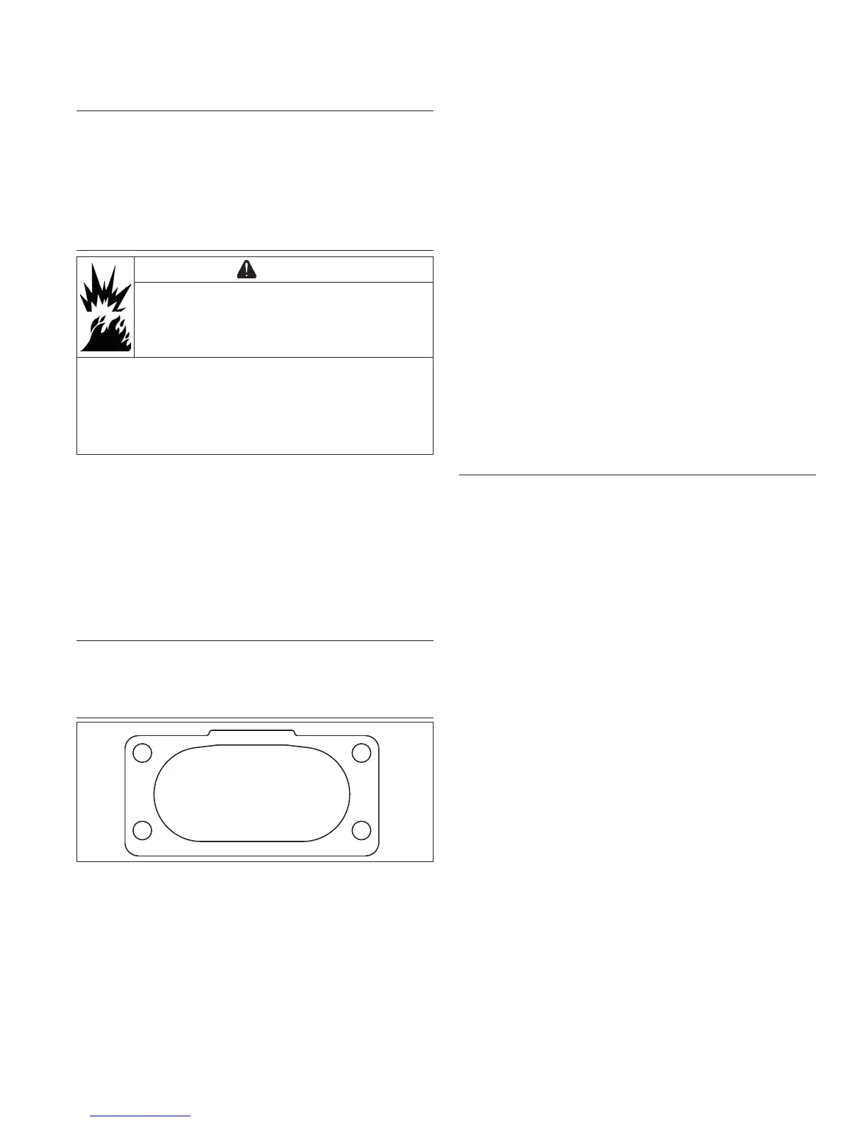
1. Install a new carburetor gasket onto intake manifold
with tab up. Make sure all holes align and are open.
2. Attach choke return spring and bracket to front hole
in choke lever on carburetor.
3. Connect throttle and choke linkages to carburetor if
they were previously disconnected. Install carburetor
with linkages attached as an assembly.
4. Connect fuel line to carburetor inlet and secure with
a clamp.
Install Governor Lever
Install governor lever onto governor shaft and connect
throttle linkage with black clip. Do not tighten governor
lever at this time.
Install Control Bracket and Air Cleaner Assembly
1, 5
4
3
2
NOTE: Low-profi le air cleaner is installed similarly to
Heavy-duty air cleaner.
1. Position control bracket assembly onto two intake
manifold bosses. Align rear supports with top valley
baffl e/cylinder head mounting screw locations and
install two screws, but do not fully tighten.
2. Connect choke link to control pivot pin. Reinstall
washer and secure with a new push-on pal nut.
3. Install a new air cleaner elbow gasket onto
carburetor mounting studs.
4. Slide air cleaner assembly onto four carburetor
mounting studs. Align two forward mounting holes in
base with mounting holes/bosses of intake manifold
and control bracket. Attach ground lead under hex
nut as originally installed. Install remaining three hex
nuts and start two hex fl ange screws. Install rear
mounting screws into valley baffl e/cylinder head.
Check positions of all parts then tighten four hex
fl ange nuts to torque specifi cation in sequence
shown, and four hex fl ange screws to torque
specifi cation.
5. Connect breather hose to fi tting on air cleaner outlet
and connect fuel solenoid lead.
6. Connect formed vent hose to air cleaner housing
and vent port on carburetor.
Install Throttle and Choke Linkages
If individual throttle/choke lever control linkages were
disconnected during disassembly, reconnect them based
on operating direction of control cables to be used.
On Control Levers:
Hole A is used for Outer Pull control cable actuation.
Hole B is used for Inner Pull control cable actuation.
1. Connect choke linkage to appropriate hole in choke
lever and secure with small clip.
2. Connect throttle linkage to appropriate hole in
throttle lever and secure with small clip.
Adjusting Governor
1. Position governor lever so clamping area is inboard
but completely on knurled area of governor cross
shaft.
2. Move governor lever toward carburetor as far as it
will go (wide-open throttle) and hold in position.
3. Insert a long thin rod or tool into hole on cross shaft
and rotate shaft clockwise (viewed from end) as far
as it will turn, then tighten to torque specifi cation.
4. Ensure correct color springs are used. Connect
governor spring (with long looped end), to inner hole
on governor lever and control bracket.
Connect governed idle spring to outer governor lever
hole and control bracket. Long end of each spring
must be toward governor lever. Make sure springs
do not contact valley baffl e.
 Loading...