62
Reassembly
KohlerEngines.com 62 690 01 Rev. C
Install Outer Cylinder Baffl es
1. Install outer cylinder baffl es. Make sure spark plug
lead is routed through corresponding opening in
each baffl e. Start each screw. Tighten M6 shoulder
screws going through backing shroud assembly into
extruded holes in baffl es to torque specifi cations.
Tighten M6 screws going into cylinder head and
crankcase to torque specifi cations.
Install Oil Cooler
1. Connect two hoses between oil fi lter adapter and oil
cooler. Secure with new clamps.
2. Align oil cooler with bosses in backing shroud
assembly. Secure with two screws and washers.
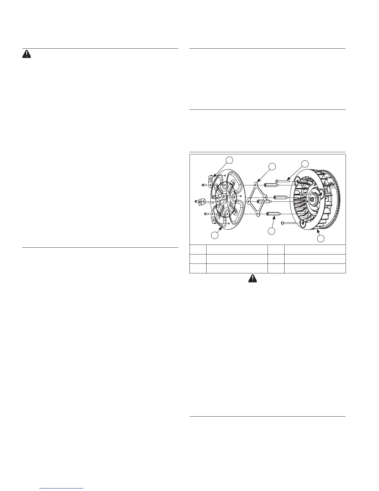
Install Cooling Fan and Grass Screen
F
E
D
C
B
A
A Special Washers B Stiffener
C Fan Screws D Fan
E Mounting Studs F Grass Screen
CAUTION
Failure to utilize or reassemble grass screen as
designed could result in grass screen failure and serious
personal injury.
1. Position cooling fan onto fl ywheel aligning mounting
locations. Apply a small amount of Loctite
®
243™
Threadlocker to threads and install three long
mounting screws. Tighten screws to torque
specifi cation.
2. Apply a small amount of Loctite
®
243™ Threadlocker
to external threaded section, (unless new parts with
preapplied locking compound are being used).
Thread four grass screen hex studs into mounting
holes in fl ywheel. Tighten each stud to torque
specifi cation.
3. Install stiffener followed by metal grass screen onto
four hex studs. Secure with four special washers and
mounting screws using Loctite
®
243™ Threadlocker
on threads. Tighten screws to torque specifi cation.
Install Electric Starter
1. Install electric starter motor using two hex fl ange
screws.
2. Tighten hex fl ange screws to torque specifi cation.
3. Connect leads to solenoid.
Install Flywheel
WARNING: Damaging Crankshaft and Flywheel Can
Cause Personal Injury!
Using improper procedures to install fl ywheel can
crack or damage crankshaft and/or fl ywheel. This not
only causes extensive engine damage, but can also
cause personal injury, since broken fragments could be
thrown from engine. Always observe and use following
precautions and procedures when installing fl ywheel.
NOTE: Before installing fl ywheel make sure crankshaft
taper and fl ywheel hub are clean, dry, and
completely free of any lubricants. Presence of
lubricants can cause fl ywheel to be over
stressed and damaged when hex fl ange screw
is torqued to specifi cations.
NOTE: Make sure fl ywheel key is installed properly in
keyway. Flywheel can become cracked or
damaged if key is not properly installed.
1. Install woodruff key into crankshaft keyway. Make
sure key is properly seated and parallel with shaft
taper.
2. Install fl ywheel onto crankshaft, being careful not to
shift woodruff key.
3. Install hex fl ange screw and washer.
4. Use a fl ywheel strap wrench or holding tool to hold
fl ywheel. Tighten hex fl ange screw to torque
specifi cation.
Install Ignition Modules
1. Rotate fl ywheel to position magnet away from
ignition module bosses.
2. Connect ground lead to single kill tab and install
modules onto crankcase bosses so tab is away from
you (in). Spark plug lead should be towards you
(out). Mount wiring harness clamp with loop up, on
starter (No. 1) side inner module screw and route
harness through it. Attach rectifi er-regulator ground
lead to outer screw.
3. Slide modules up as far away from fl ywheel as
possible and snug screws to hold them in position.
4. Rotate fl ywheel to position magnet directly under
one ignition module.
5. Insert a 0.30 mm (0.012 in.) fl at feeler gauge
between magnet and ignition module. Loosen
screws enough to allow magnet to pull module down
against feeler gauge.
6. Tighten screws to torque specifi cation.
7. Repeat Steps 4 through 6 for other ignition module.
8. Rotate fl ywheel back and forth, checking for
clearance between magnet and ignition modules.
Make sure magnet does not strike modules. Check
gap with a feeler gauge and readjust if necessary.
Final Air Gap: 0.280/0.330 mm (0.011/0.013 in.).
9. Make sure leads are under molded clip on starter
side.
 Loading...