4.
Install gasket and governor then secure to gear cover with two capscrews.
Before closin
g
gear cover sight hole with plug, check to make sure beveled tooth on cam can he observed
in hole.
5.
Ignition timing must be readjusted after governor is installed.
On the K482 and
K532, this
is
done by loosening the capscrews and rotating governor
--
see Ignition Timing instructions
(Section 6) for exact details.
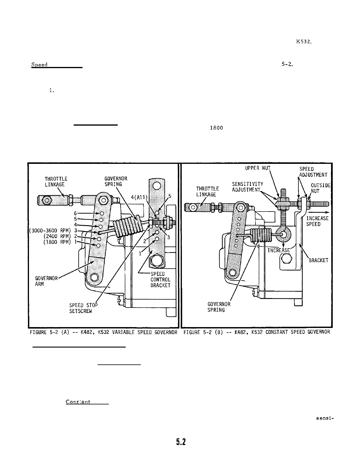
Speed Adjustment:
On most engines with the variable speed type governor (See Figure
5-2, View
A),
maximum speed is set at 3600 RPM no load.
On
some applications, a lower maximum speed is specified
-
-
make sure that the allowable speed for the particular application is not exceeded. Use the following
procedure to readjust speed Limit on engines with the variable speed governor:
1. Start engine and operate at full throttle (no load).
2. Check engine speed with hand tachometer
-
-
if within
50
RPM of specified limit, readjust
-
ment
is
not absolutely necessary.
3.
Loosen locking nuts on speed stop setscrew
-
-
turn screw out or in as necessary to attain
specified top speed. Retighten locking nuts to secure stop at new setting.
With the Constant Speed type governor (Figure 5
-
2
-
-
View
B),
the throttle shaft is fixed at a
definite length to establish a specific operating speed such as
1800 RPM for 60 cycle electric plants.
Any variation in speed causes frequency changes in output of the generator
--
for this reason, only slight
readjustment of speed
is
possible with constant speed governors.
To increase speed, loosen the inside
speed adjusting locking nut and tighten the outside nut to draw the eye of the holt closer to the bracket
-
-
to aecrease speed, loosen the outside nut and tighten the inside nut.
After speed is correct, tighten
the nut that was loosened to lock the eye bolt at the new setting.
Governor Sensitivity Adjustment:
If the governor is too sensitive, speed surging will occur with change
in load.
If a big drop in speed occurs when normal load is a
pp
lied, the governor should be set for
greater sensitivity.
On engines with Variable Speed governors, sensitivity can be adjusted by repositioning the gover
-
nor spring in different holes in the governor arm.
Normal hole settings for different operating speeds
are shown in View A of Figure 5
-
2.
To make governor control more sensitive, move spring hook into
holes higher up on the governor arm.
To make governor control less sensitive, move spring hook in
holes spaced further apart. Move spring one hole at a time and recheck sensitivity and speed after
each move.
With
Conrlant Speed governors, sensitivity is changed by repositioning the sensitivity adjusting
eye holt as shown in Figure 5
-
2
--
View
B.
To make governor control more sensitive, loosen the upper
nut and tighten the lower nut to force the eye bolt downward.
To make control less sensitive, draw the
eye holt upward by loosening the lower nut and tighten the upper nut.
Recheck speed after making
sensi-
tivity adjustment. Retighten nut that was loosened to lock eye bolt at the new setting.
 Loading...