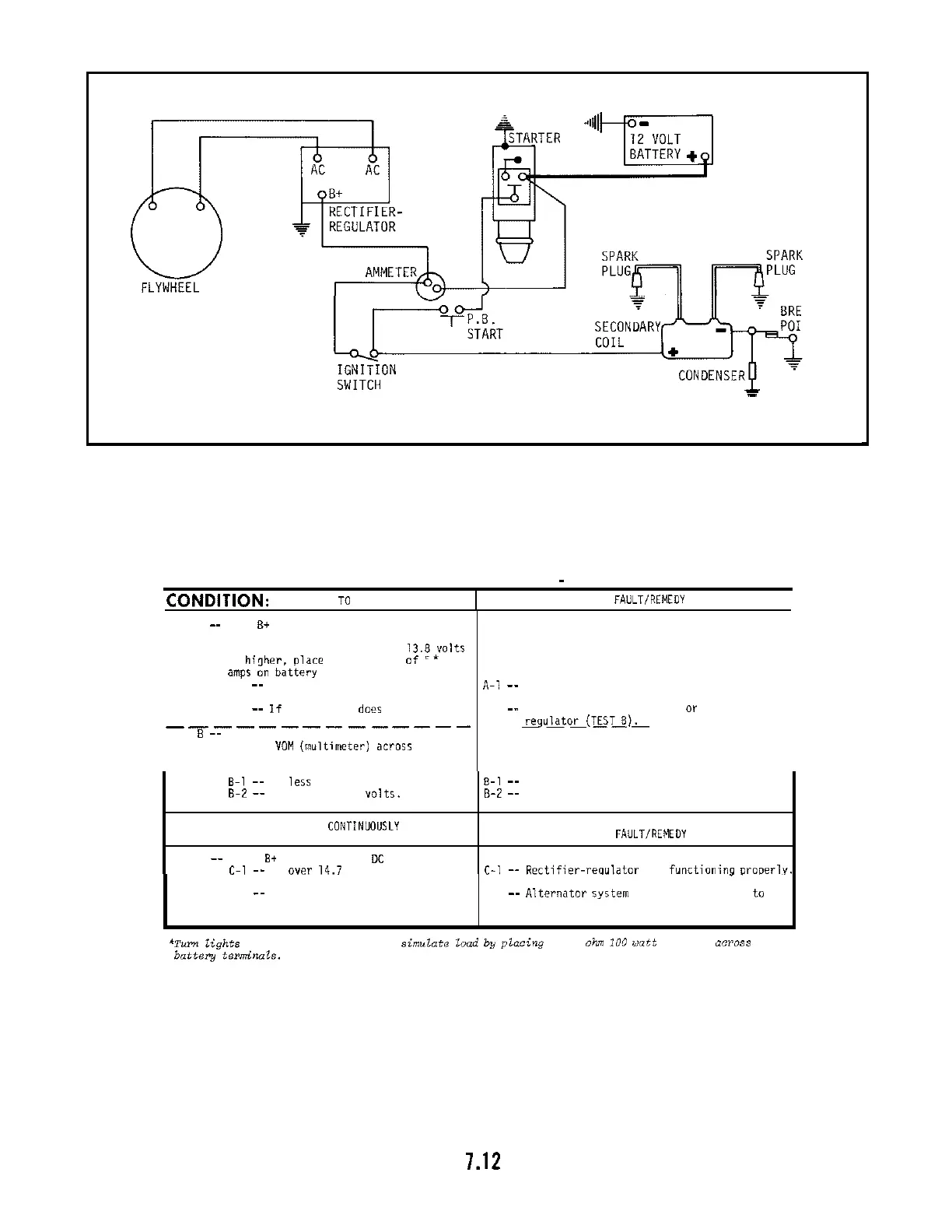
ALTERNATOR
AKER
NTS
-
-
-
-
FIGURE
7
-
14
--
TYPICAL
15
AMP SYSTEM, WIRING DIAGRAM
I
TEST A
--
With B+ cable connected,
check
Bt (at
terminal
an
rectifier
-
regulator) to
ground with DC Voltmeter.
If
13.82olts
or
hioher.
olace minimum load
of
5
TROUBLE SHOOTING
-
15
AMP SYSTEM
TEST WITH ENGINE RUNNING AT 3600 RPM
-
NO LOAD
amps
on
battery to
reduce
voltage:
A
-
1
--
If
charge rate
increases.
CONDITION:
NO CHARGE TO BATTERY
I
A
-
2
--
If
charge rate does not
increase.
POSSIBLE FAULTIREMEDY
I
-
-
- -
-
-
-
- -
-
-
-
-
-
TEST B
--
Unplug leads at rectifier
-
regulator,
connect
VOM (multimeter)
across
AC
leads, check AC voltage:
I
.
A-1
--
Indicates alternator system OK, battery
was
fully charged.
A
-
2
--
Check for defective stator
or
rectifier
-
--
%ulato~(T~TL!)~
-
-
-
-
- -
I
8-1
--
If
less than 28 volts.
8-2
--
If
more
than 28 volts.
CONDITION:
B
A
TTERY
CONTINUOU~LY
CHARGES AT HIGH RATE
TEST C
--
Check
B+
to
ground with
DC
Voltmeter:
C-l
--
If
over
14.7 volts.
'Turn
lights
on
if 60 watts
or
more
or
simulate Zood
by
pZacing
a
2.5
ohn
I00
watt resistor
across
batteiy
terminots.
B-1
--
Defective stator,
replace
with
new
assembly.
8-2
--
Defective rectifier
-
regulator, replace with
new
unit.
POSSIBLE
FAULTIREMEDY
C-1
--
Rectifier-requlatar not functioninq ~ra~erly.
C
-
2
--
if
under 14.7 volts.
.. .
.
Replace with
-
new unit.
C
-
2
--
Alte~nato~ system OK. Battery unable to
hold charge. Check specific gravity
of
battery. Replace
if
necessary.

 Loading...