Trouble Shooting:
If engine fails to start after ascertaining that fuel reaches solenoid inlet,
first check that solenoid is operating; an audible click will be beard when solenoid is energized.
In the event that still no fuel flows from outlet of regulator, the difficulty may be traced to a
sticky valve disc in solenoid assembly.
If engine does not idle with adjusting screw in any position, the trouble, most likely, can
be traced to the low pressure valve, as dirt or foreign matter may have become lodged
on
the
seat.
This can he remedied by washing the valve and seat in
a
solvent.
Service Instructions:
It is preferable to have the LP
-
gas regulating unit serviced by dealer with
with parts and facilities for testing.
However, if this is not possible, proceed as follows:
Completely disassemble the model RCB unit.
Thoroughly wash all parts and blow out all
passageways with compressed air.
It is suggested that a repair kit be used in reassembling the regulator.
The use of short pins
(2" long),
inserted in threaded screw holes of casting, will materially
aid in the installation of gaskets and diaphragms.
When replacing the high pressure valve assembly, make certain that machined seat in
casting is perfectly clean and free of nicks.
Wipe out any foreign matter which could
affect
DrODer seatine of valve bodv and O-ring. ADDIV a small amount of oil to O-ring to
. .
u
"
..
.
-
aid in the initial sealing.
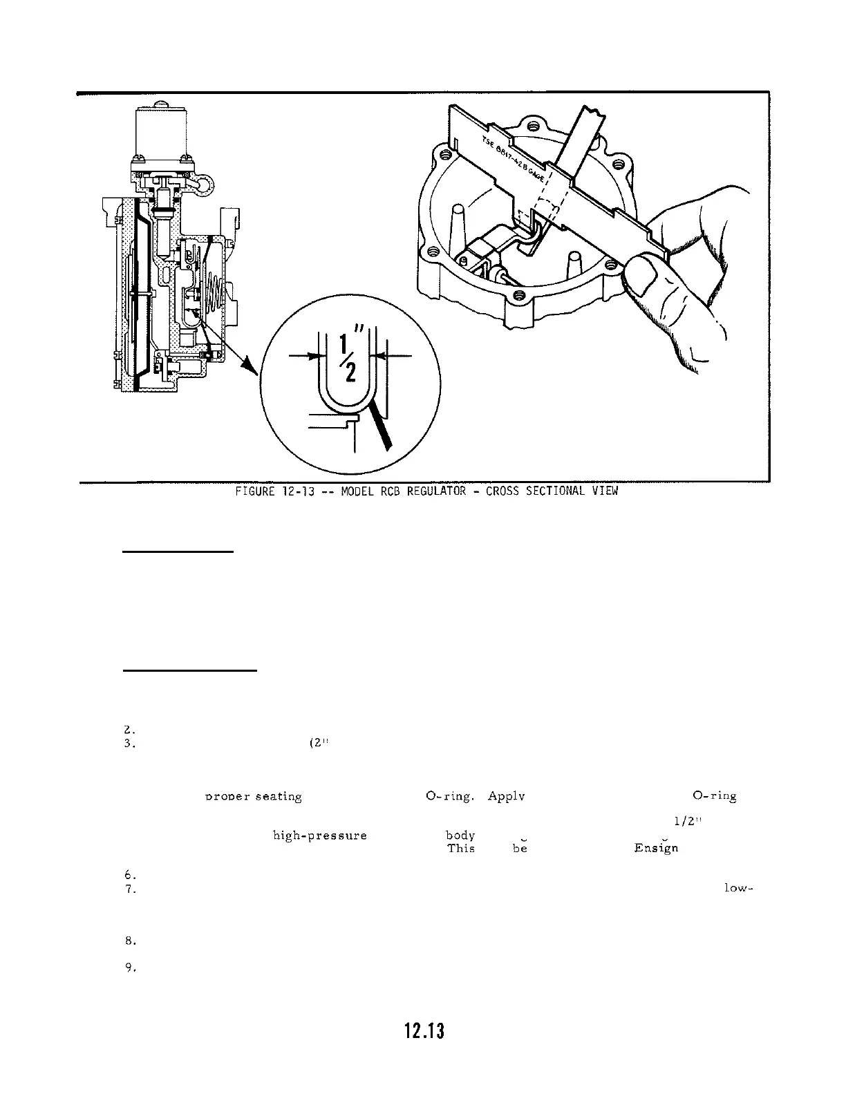
Carefully note the dimension shown on insert Figure 12
-
13. This should be 1/2" as indi
-
cated, from the hieh-oressure side of the bod" castine to the inside of the groove in valve
u.
lever when the valve is held firmly shut.
hi;
may be measured with ~nsgn Gauge TSE
8817
-
42B.
Completely assemble the high
-
pressure section before proceeding further.
A
post or boss is machined and marked with an arrow for the purpose of setting the low-
pressure valve lever. The valve lever should be centered on the arrow before tightening
the screws holding the valve block. Top of
lever
should be flush with the top of the post.
Bend the valve lever, if necessary, to the correct height.
The push pin in lever must be centered through hole in partition plate.
Re
-
align low pres
-
sure lever if necessary by shifting valve assembly and retightening screws.
The push pin must be positively fastened to diaphragm plate with spring washer and cotter
pin.
 Loading...