- 22 -
KD 477-2 Workshop Manual_cod. ED0053029370_1° ed_ rev. 00
X
20
21
22
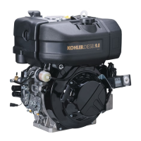
21,997 ÷ 22,002 0,023 ÷ 0,038 0,070
Engine
Ø Piston pin
mm
Assy. clearance
mm
Max wear
mm
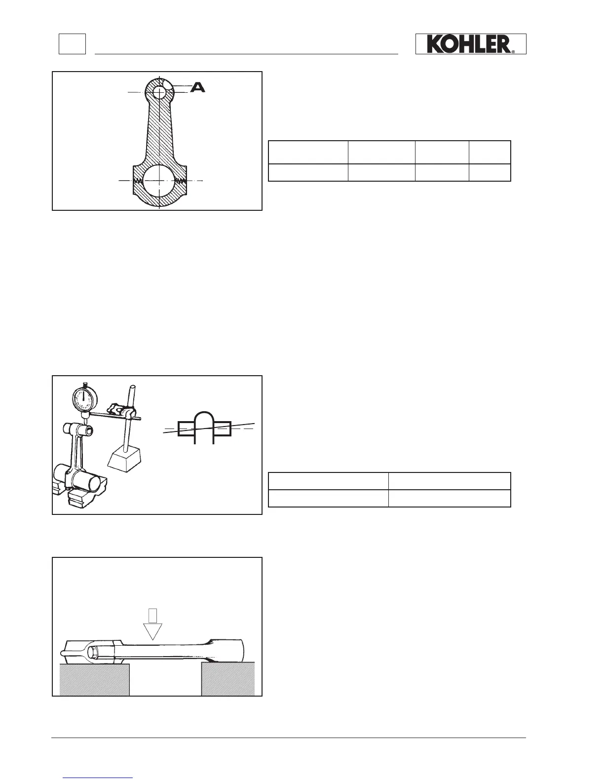
Engine Weight
If it is necessary to replace a complete connecting rod with bushes
and bolts, make sure its weight is:
Check parallelism between connecting rod axies (g. 21) as follows:
1
. Insert the gudgeon pin into the small end bush and a calibrated
pin into the big end (with bearing tted).
2. Place the ends of the pin on 2 prisms set out on a checking
bench.
3. Check with a comparator gauge that the discrepancy in the rea-
dings at the two ends of the gudgeon pin is not more than 0.05
mm. Should the distortion exceed this value (max 0.10 mm), re-
set connecting rod as follows:
Place connecting rod stem on checking bench and apply a cali-
brated pressure to the convex side of the stem (g. 22).
CHECKS AND OVERHAUL
Connecting rods
On the small end there is a groove (A, g. 20) for the lubrication of
the gudgeon pin. The small end and the gudgeon pin are coupled wi-
thout a bush in between.
Assembly clearance between connecting rod small end and piston
pin in millimetres:
KD 477-2
KD 477-2 gr. 570 ± 10
 Loading...