MAINTENANCE
TP-6901 3/16a Maintenance 37
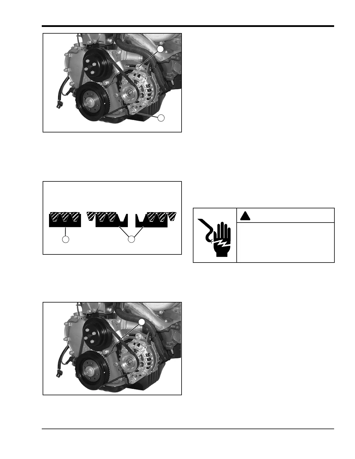
Figure5-18
1. Loosen the two alternator mounting bolts (A) on the
alternator and mounting bracket. See Figure 5-18.
2. Remove and discard the old drive belt.
Figure5-19
3. Place the new drive belt on the pulleys. Make sure
that the belt is properly aligned with the grooves on
each pulley. See Figure 5-19.
Figure5-20
4. Set drive belt tension to specification. See Figure
5-20.
• Apply specified pressure to the drive belt at its
midpoint. At the same time, measure the
amount of deflection of the drive belt at its
midpoint (D). Deflection should be within
specification.
DRIVE BELT TENSION
Applied Test Pressure
98 N (22 lb.)
Belt Deflection - New
5–7 mm (0.20–0.28 in.)
Belt Deflection - Used
7–8 mm (0.28–0.31 in.)
5. Tighten the two alternator mounting bolts.
6. Check the drive belt tension and adjust the
alternator position as needed until correct drive belt
tension is reached.
Check Wiring and Electrical
Connections
Check the condition of the wiring and electrical
connections after every 10 hours of operation. Specific
items to look for are:
• Exposed (bare) wires.
• Cuts or abrasions in wire insulation.
• Loose connections at screw terminals.
• Loose, dirty, or cracked electrical connectors.
• Melted or scorched wiring, insulation, or
connectors.
Repair or replace faulty electrical components before
operating the machine.
B Correct C Incorrect
Electrical shock can cause injury.
Do not touch wires while engine is
running.
 Loading...