36
Disassembly/Inspection and Service
KohlerEngines.com 14 690 01 Rev. G
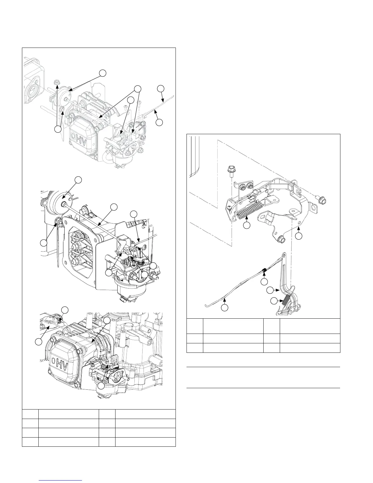
Remove Carburetor with Auto Choke (if equipped)
B
C
A
F
E
D
G
E
F
A
H
B
C
A Nut(s) B Arm Assembly
C Linkage D Choke Linkage
E Governor Linkage F Linkage Spring
G Wire Choke Linkage H Choke Link
1. Remove screws securing arm assembly to
carburetor.
2. Disconnect fuel line.
3. Remove wire choke linkage while sliding carburetor
away from engine a couple of inches.
4. Disconnect governor linkage and linkage spring from
carburetor.
5. Remove carburetor.
6. Remove nuts securing arm assembly to mufer.
Second nut is located behind arm assembly base
securing it to top of mufer.
7. Remove arm assembly from mufer.
Control Components
D
E
F
C
B
A
A Flywheel Brake
Spring
B Speed Control
Bracket
C Linkage Spring D Governor Lever
E Governor Spring F Throttle Linkage
Remove Speed Control Bracket
Disconnect governor spring from speed control bracket.
Remove Speed Control Bracket
NOTE:
Fuel hose connecting carburetor and fuel tank is
held in place by a plastic ring, mounted on back of
speed control bracket. If bracket is removed from
crankcase, it will remain attached to fuel hose (not
including California engines). Should replacement
of speed bracket be required, disconnect fuel line
from fuel lter or carburetor and slide bracket off
hose. Do not disconnect fuel hose from fuel tank.
Remove screws securing speed control bracket.
B
A
C
H
 Loading...