50
Reassembly
KohlerEngines.com 14 690 01 Rev. G
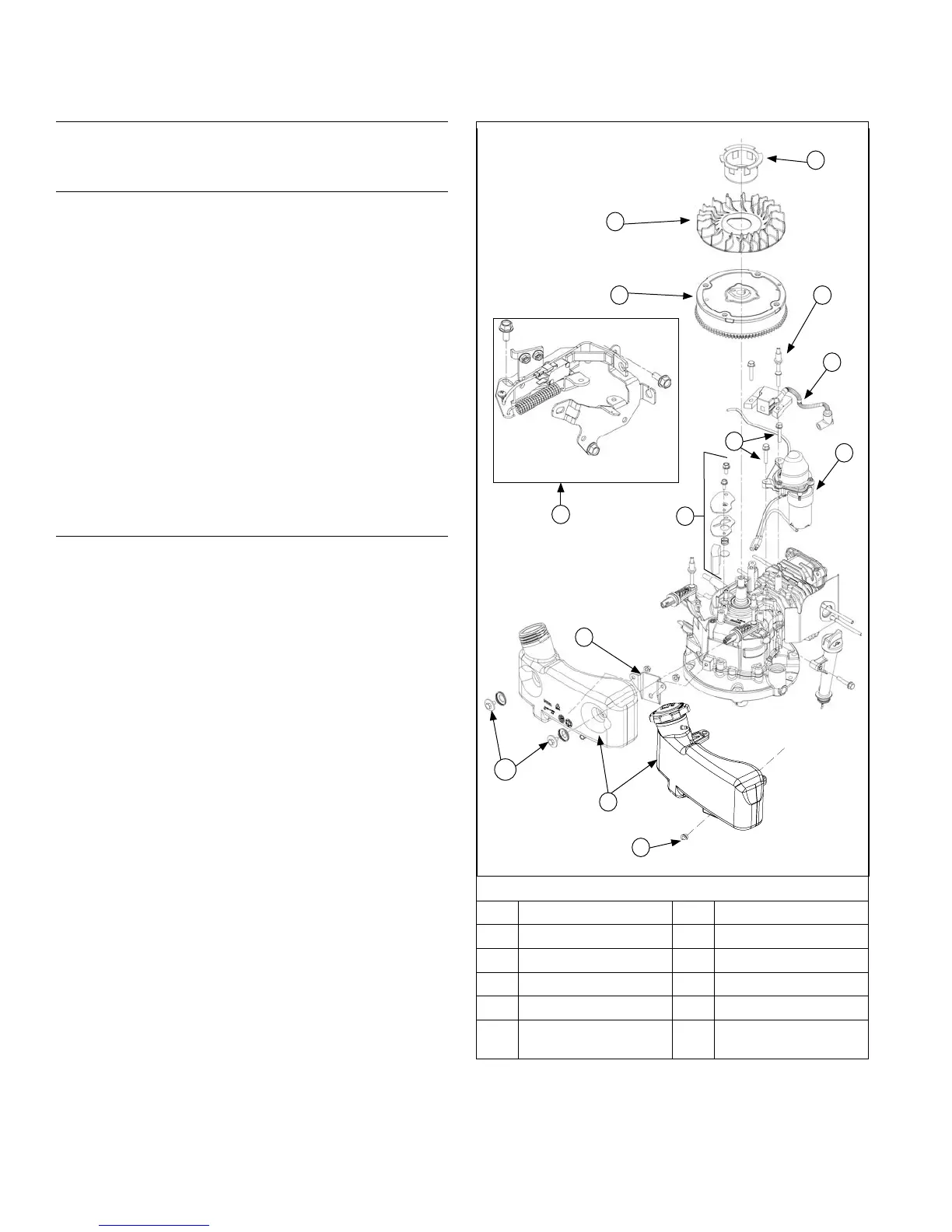
Flywheel/Ignition/Fuel Tank Components
G
H
I
E
L
C
B
K
F
D
J
A
A Screws B Fuel Tank
C Crankcase Bracket D Electric Starter
E Ignition Module F Stud(s)
G Drive Cup H Fan
I Flywheel J Screw(s)
K
Flywheel Brake
Assembly
L Breather Assembly
Install New Spark Plug
1. Set gap of a new spark plug to 0.76 mm (0.03 in.).
2. Install spark plug and torque to 27 N·m (20 ft. lb.).
Install Flywheel Brake Assembly
Dipstick Side of Engine
1. Install spacers onto brake assembly screws.
Fuel Cap Side of Engine
1. Place brake assembly onto engine and loosely
install 2 brake assembly screws.
2. Install a caliper between brake lever and bracket to
establish a 50 mm (1.968 in.) gap, pivoting on rear
screw if necessary.
3. Rotate brake lever clockwise around rear screw.
Torque screws to 9.5 N·m (84 in. lb.). Reinstall kill
lead to ignition module or to bottom terminal on
micro switch (if equipped).
4. Actuate brake arm and verify an audible click is
heard from micro switch (if equipped). Visually
inspect all wires are connected and micro switch is
moving up and down when brake arm is pulled. If an
audible click from micro switch is not heard, loosen
both screws and readjust.
Install Breather Assembly
1. Install breather disc and spring.
2. Install breather screen.
3. Install breather cover and secure with screws.
Torque screws to 10 N·m (88 in. lb.).
A
 Loading...