.
OPERATION
EXPLANATION OF COMPONENTS
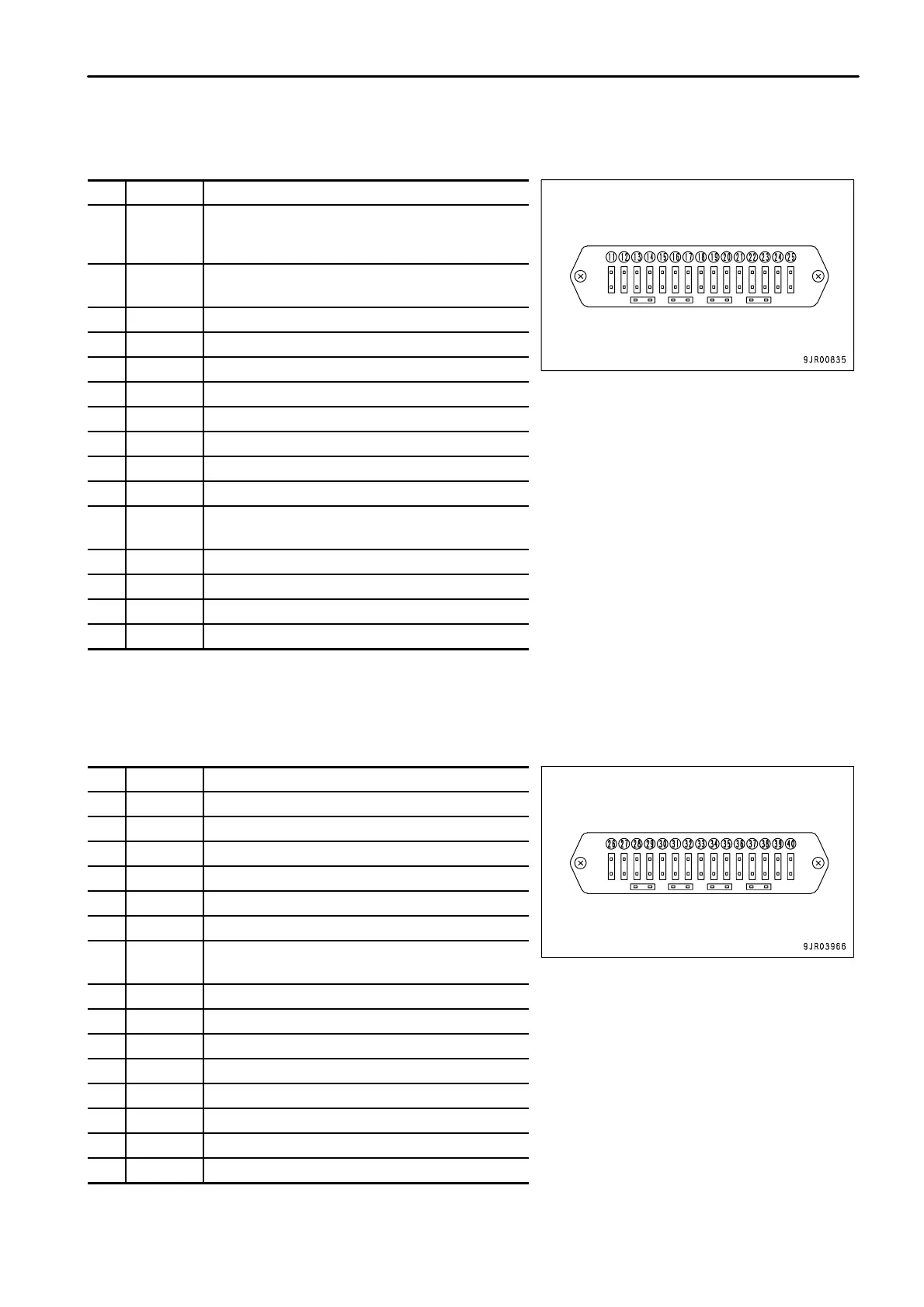
Fuse box II
No. Capacity Name of circuit
(11) 10A
Machine monitor,
Payload meter II (if equipped),
Controller (if equipped)
(12) 10A
Rear view monitor (if equipped)
Download ACC
(13) 10A Parking brake circuit
(14) 20A Power window (left)
(15) 20A Power window (right)
(16) 10A Payload meter II controller (if equipped)
(17) 10A Horn
(18) 10A Machine monitor
(19) 10A Transmission controller
(20) 20A B terminal
(21) 10A
Retarder controller
ABS controller (if equipped)
(22) 20A Hazard lamp
(23) 10A Emergency steering
(24) 10A Room lamp, Radio
(25) 10A Machine monitor, KOMTRAX (if equipped)
Fuse box III
No. Capacity Name of circuit
(26) 20A Fog lamp (if equipped)
(27) 20A Air conditioner controller (if equipped)
(28) 20A Heater (if equipped)
(29) 20A Heater (if equipped)
(30) 20A ABS controller (if equipped)
(31) 20A Retarder controller
(32) 10A
Transmission controller,
Power source for gear shift lever
(33) 10A Emergency steering, Parking brake relay
(34) 10A Radio (if equipped)
(35) 10A Engine controller
(36) 30A Engine controller
(37) - -
(38) - -
(39) 10A KOMTRAX (if equipped)
(40) 20A Spare
3 - 47

 Loading...