5 Installation at Site
31 of 92
KSB Delta Macro
1983.843/04-EN
5.5.2 Connecting the pressure booster system
ü The pressure booster system can be operated on the power supply network in
accordance with the data on the name plate.
ü The wiring diagram is available.
1. Connect terminals L1, L2, L3, PE and N in accordance with the wiring plan.
2. Connect the potential equalisation conductor on the baseplate to the terminal
with the earthing symbol.
ð The earthing connection is located underneath the control cabinet.
Optionally, a connection is located at the manifold.
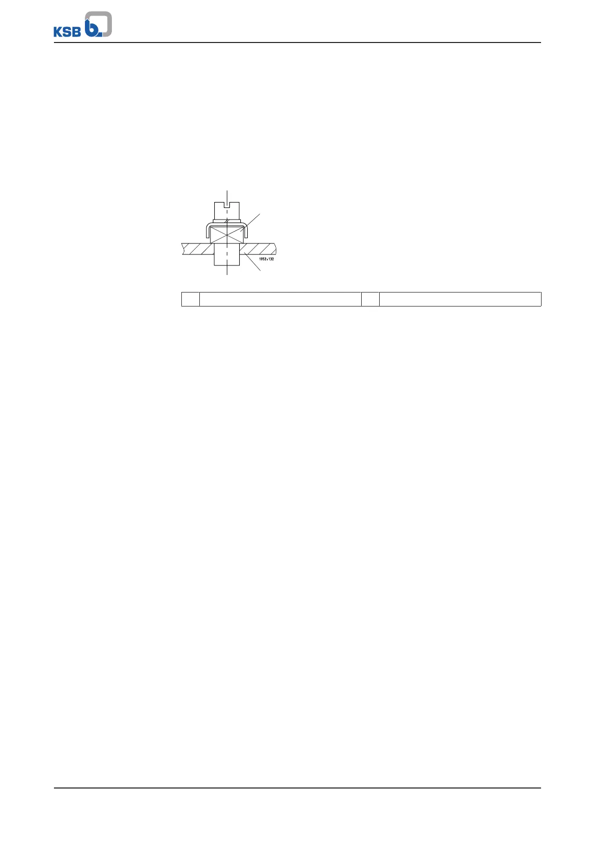
Fig.14: Connecting the potential equalisation conductor
1 Earthing terminal 2 Baseplate
3. Connect the remote ON/OFF input. (ðSection5.5.3,Page31)
4. Connect the dry running protection device. (ðSection5.5.4,Page31)
5.5.3 Connecting the remote ON/OFF input
1. Establish the connection in accordance with the wiring diagram.
5.5.4 Connecting the dry running protection device
ü The original operating manual of the dry running protection device is on hand.
1. Fit the dry running protection device in accordance with the supplied original
operating manual. Connect it in the control unit in accordance with the supplied
original operating manual.
 Loading...