7 Operation
38 of 92
KSB Delta Macro
1983.843/04-EN
7 Operation
7.1 Control panel
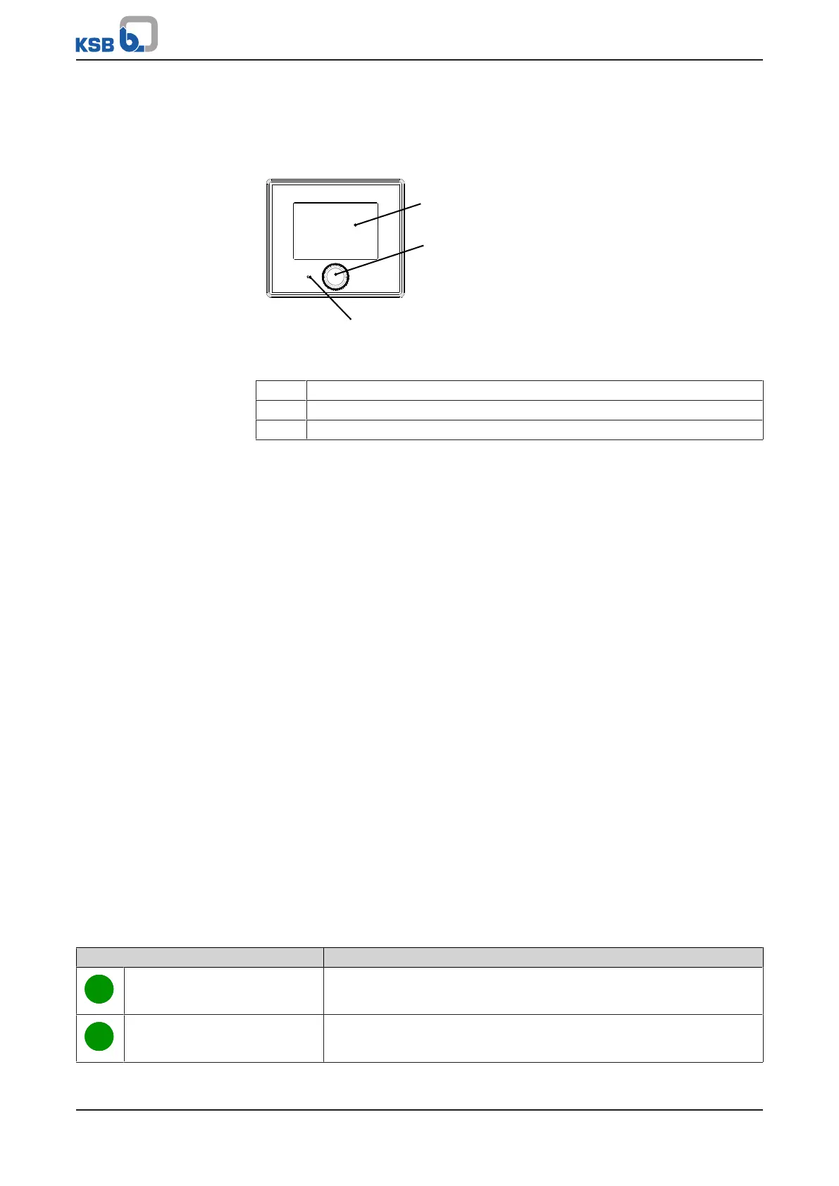
Fig.16: Control panel
1 Screen (ðSection7.1.1,Page38)
2 Turn/push button (ðSection7.1.2,Page38)
3 Status LED (ðSection7.1.3,Page38)
7.1.1 Screen
To save power the screen is turned off automatically.
To turn on the screen push or turn the turn/push button arranged below the screen.
If a message is active, the screen also lights up and displays the current message ID as
well as the system status.
7.1.2 Turn/push button
The turn/push button serves to make a selection on the screen. The initial movement
of the turn/push button activates its function. The symbol selected on the screen
flashes briefly.
Starting point The starting symbol is always the lock/unlock symbol.
Turning the turn/push
button
Turning the turn/push button makes all selectable symbols flash one after the other
in a specific sequence, depending on the system configuration.
After the flashing cycle of all selectable symbols has been completed, the selection
returns to the lock/unlock symbol.
To increase a value turn the turn/push button clockwise. To decrease a value turn the
turn/push button anti-clockwise.
Pressing the turn/push
button
A selected symbol can be confirmed by pressing the turn/push button.
Depending on the symbol, a setting is displayed or a selection can be made.
7.1.3 Status LED
When the screen is not lit, the status LED shows that the system is energised and that
the control unit is in operation. The LED is only lit when the screen is not. Based on a
traffic light system, the colour indicates the system status.
Table14: Explanation of the status LED
Colour of the status LED Description
Green (flashing) System in operation, no messages are active.
Green (continuous) One or more information messages are active.
 Loading...