7 Operation
41 of 92
KSB Delta Macro
1983.843/04-EN
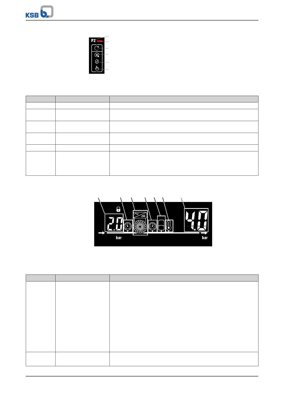
Fig.18: Operating status of pump set P2
Table18: Pump operating status symbols
Position Refers to Description
1 Pump set in the system Symbols for a specific pump set (in this example pump set2)
2 Active messages One or more warning messages or alert messages are active for pump
set2.
3 Pump set running Indicates whether the pump set is currently running. This symbol is
extinguishes when the pump set has been stopped or is in idle state.
4 Automatic mode The pump set is started up and stopped via the control unit (Fsystem) or
via a frequency inverter (VC and SVP systems).
5 Manual OFF Pump start-up is locked. If a pump set is running, it will be stopped.
6 Manual ON The pump set is started up manually.
In the case of an Fsystem, the pump is started up. In the case of a VC or
SVPsystem, the pump starts running at a fixed frequency (fixed speed).
The fixed frequency can be configured.
7.2.5 Information on the system
Fig.19: Information on the system
Table19: Symbols for information on the system
Position Refers to Description
1 Display for suction-side
sensors
Depending on the connected sensors the following values are displayed:
▪ Version with pressure gauge: Displays the pressure at the inlet of the
pressure booster system.
▪ Version with pressure switch/ float switch/ flow monitor: Displays
the digital input signal Hi or Lo.
If several sensors are used, the values are displayed alternately.
▪ PIN display
– For connecting the control unit to the mobile device. (The
complete PIN is composed of this PIN and the PIN in position7.)
▪ Display of the firmware version (The total firmware version is
composed of the numbers in this position and in position7.)
2 Suction-side sensor The corresponding values are shown in position1.
The corresponding messages are shown in position7.
 Loading...