THREE-POINT HITCH & DRAWBAR34
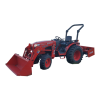
BTelescopic Stabilizers
Adjust the telescopic stabilizers to control horizontal sway
of the implement. Select the proper set of holes by
referring to the "Hydraulic Control Unit Use Reference
Chart" in "AUXILIARY HYDRAULICS" in "HYDRAULIC
UNIT" section.
After aligning satisfactorily, insert the set-pin through any
one of the eight holes on the outer tube that align with one
of the holes on the inner bar, both stabilizers will be
locked.
If the set-pin is inserted through the slot to engage one of
the holes on the inner bar, a limited degree of sway will be
permitted.
BTelescopic Lower Links
To attach an implement, follow the instructions below:
1. Push the levers, pull out the lower link ends, and
attach to the implement.
2. Back up the tractor slightly to make sure the lower links
are pushed in securely.
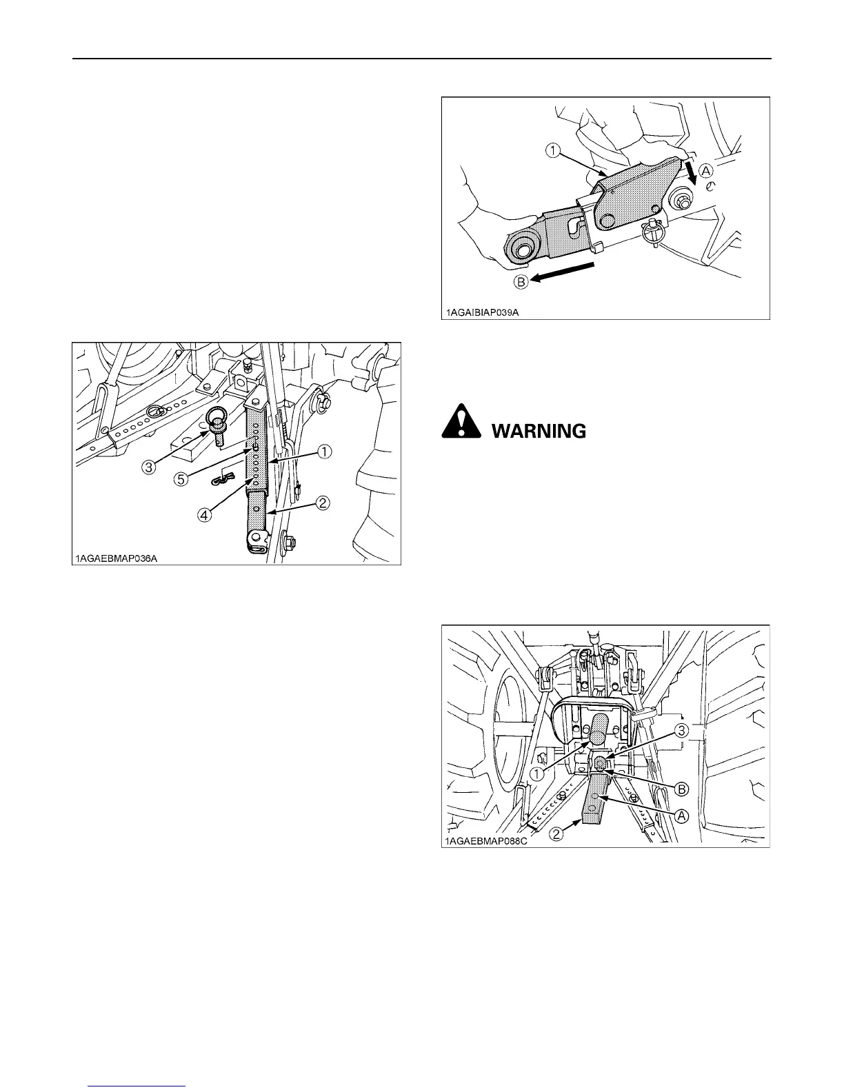
DRAWBAR
To avoid personal injury:
A Never pull from the top link, the rear axle or any
point above the drawbar. Doing so could cause
the tractor to tip over rearward causing
personal injury or death.
BAdjusting Drawbar Length
When towing an implement, use of (B) hole in drawbar is
recommended.
The acceptable drawbar load is provided in the
"IMPLEMENT LIMITATIONS" section.
(1) Outer tube
(2) Inner bar
(3) Set-pin
(4) Hole
(5) Slot
(1) Lever (A) "PUSH"
(B) "PULL OUT"
(1) PTO Shaft cap
(2) Drawbar
(3) Drawbar pin
Hole : (A), (B)
 Loading...