ENGINE
G23, G26, WSM
1-S20
(EU)
(4) Fuel System
Injection Timing
1. Remove the injection pipes.
2. Remove the engine stop solenoid.
3. Turn the flywheel counterclockwise (viewed from flywheel side)
until fuel fills up to the hole of the delivery valve holder (3) for
No.1 cylinder.
4. After the fuel fills up to the hole of the delivery valve holder for
No.1 cylinder, turn back (clockwise) the flywheel around 1.6 rad
(90 °).
5. Turn the flywheel counterclockwise to set at around 0.44 rad
(25 °) before T.D.C..
6. Slowly turn the flywheel counterclockwise and stop turning
when the fuel begins to come up, to get the present injection
timing.
7. Check to see the degree on flywheel.
The flywheel gas mark "1TC", "10" and "20" for the crank
angle before the top dead center of No.1 cylinder.
8. If injection timing is out of adjustment, readjust the timing with
shims.
• The liquid gasket is not required for assembling.
• Shims are available in thickness of 0.20 mm (0.0079 in.),
0.25 mm (0.0098 in.), 0.30 mm (0.012 in.) and 0.175 mm
(0.00689 in.). Combine these shims for adjustments.
• Addition or reduction of shim (0.05 mm, 0.002 in.) delays or
advances the injection timing by approx. 0.009 rad (0.5 °).
• In disassembling and replacing the injection pump, be sure
to use the same number of new shims with the same
thickness.
• The 0.175 mm (0.00689 in.) thick shim is coated only on the
lower face. Therefore, do not use the 0.175 mm (0.00689 in.)
thick shim as the top shim of the combination (injection
pump side), because this can cause oil leakage.
9Y1210294ENS0013US0
Injection timing
(3200 min
-1
(rpm))
Factory specification
0.3360 to 0.3622 rad
(19.25 to 20.75 °) before
T.D .C .
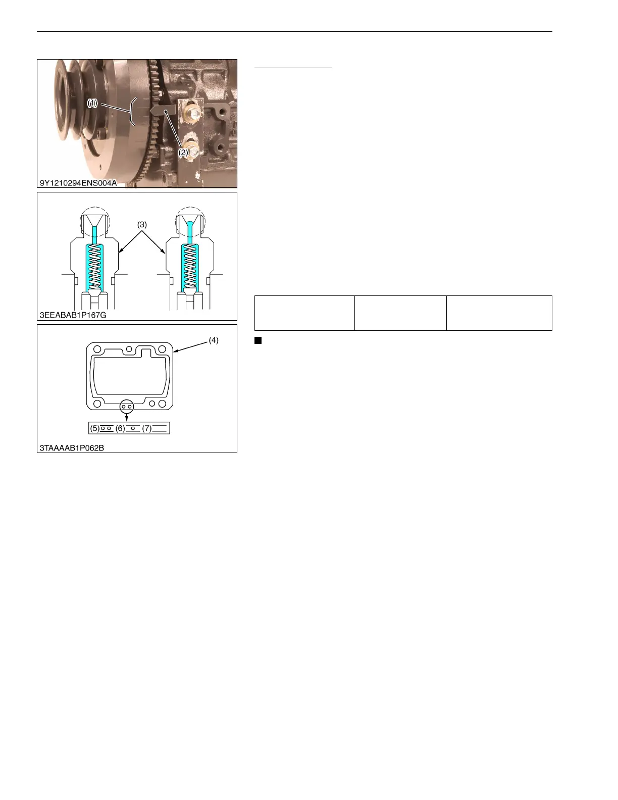
(1) Timing Line
(2) Alignment Mark
(3) Delivery Valve Holder
(4) Shim (Soft Metal Gasket Shim)
(5) Two Holes : 0.20 mm (0.0079 in.)
Two Holes : 0.175 mm (0.00689 in.)
(6) One Hole : 0.25 mm (0.0098 in.)
(7) Without Hole : 0.30 mm (0.012 in.)