HYDRAULIC SYSTEM
G23, G26, WSM
5-M8
(EU)
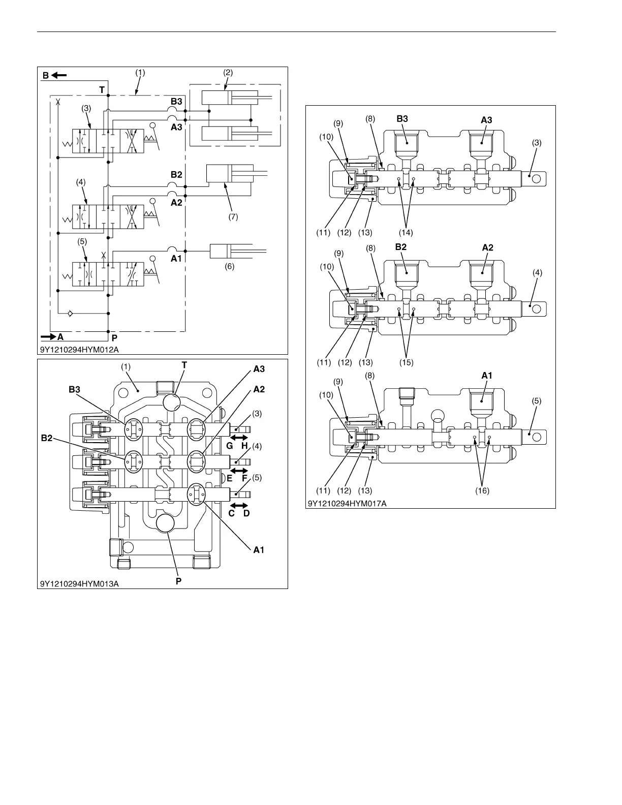
5. CONTROL VALVE
The control valve body (1) consists of the
components as shown in the hydraulic circuit and the
figure.
9Y1210294HYM0013US0
(1) Valve Body
(2) Grass Collector Lift Cylinder
(3) Spool (Grass Collector Lift
Cylinder)
(4) Spool (Dump Cylinder)
(5) Spool (Mower Lift Cylinder)
(6) Mower Lift Cylinder
(7) Dump Cylinder
(8) O-ring
(9) Return Spring
(10) Bolt
(11) Plain Washer
(12) Stop Collar
(13) Spring Cap
(14) Orifice
(15) Orifice
(16) Orifice
A : Oil from hydraulic pump
B : Oil to transmission case
P : Pump Port
T : Tank Port
A1 : Control Valve Oil Port
A2 : Control Valve Oil Port
A3 : Control Valve Oil Port
B2 : Control Valve Oil Port
B3 : Control Valve Oil Port
C, E, G : Spool is pushed into
control valve.
D, F, H : Spool is pulled out
from the control valve.
 Loading...