16 / 30 Puridest Distillation Apparatus 09/2020
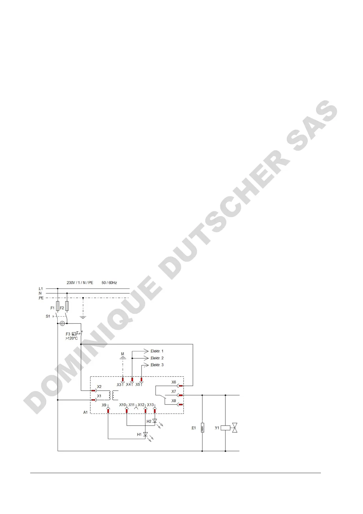
12 Circuit Diagram
A1 Electronic level switch
E1 Tubular heating element
E2 Tubular heating element
E3 Tubular heating element
H1 LED red "cleaning"
H2 LED yellow "operation"
Elektr. 1 Electrode "cleaning in boiler"
Elektr. 2 Electrode "water blocking"
Elektr. 3 Electrode "max. level storage tank"
F1 Mains fuse internal, Model PD 2 R, 10 Amp. inert
Model PD 4 R, 15 Amp. inert
F2 Mains fuse internal, Model PD 2 R, 8 Amp. inert
Model PD 4 R, 15 Amp. inert
F3 Low water cut-off (thermostat)
K1 Contactor
M Earth (housing)
S1 Main switch
Y1 Solenoid valve
PD 2 R
12.1
 Loading...