4 Operation
4.1 Setup
The first installation of the product should be done by authorised Leica Geo-
systems personnel. Installation by unauthorised personnel may cause damage
and will make the warranty null and void.
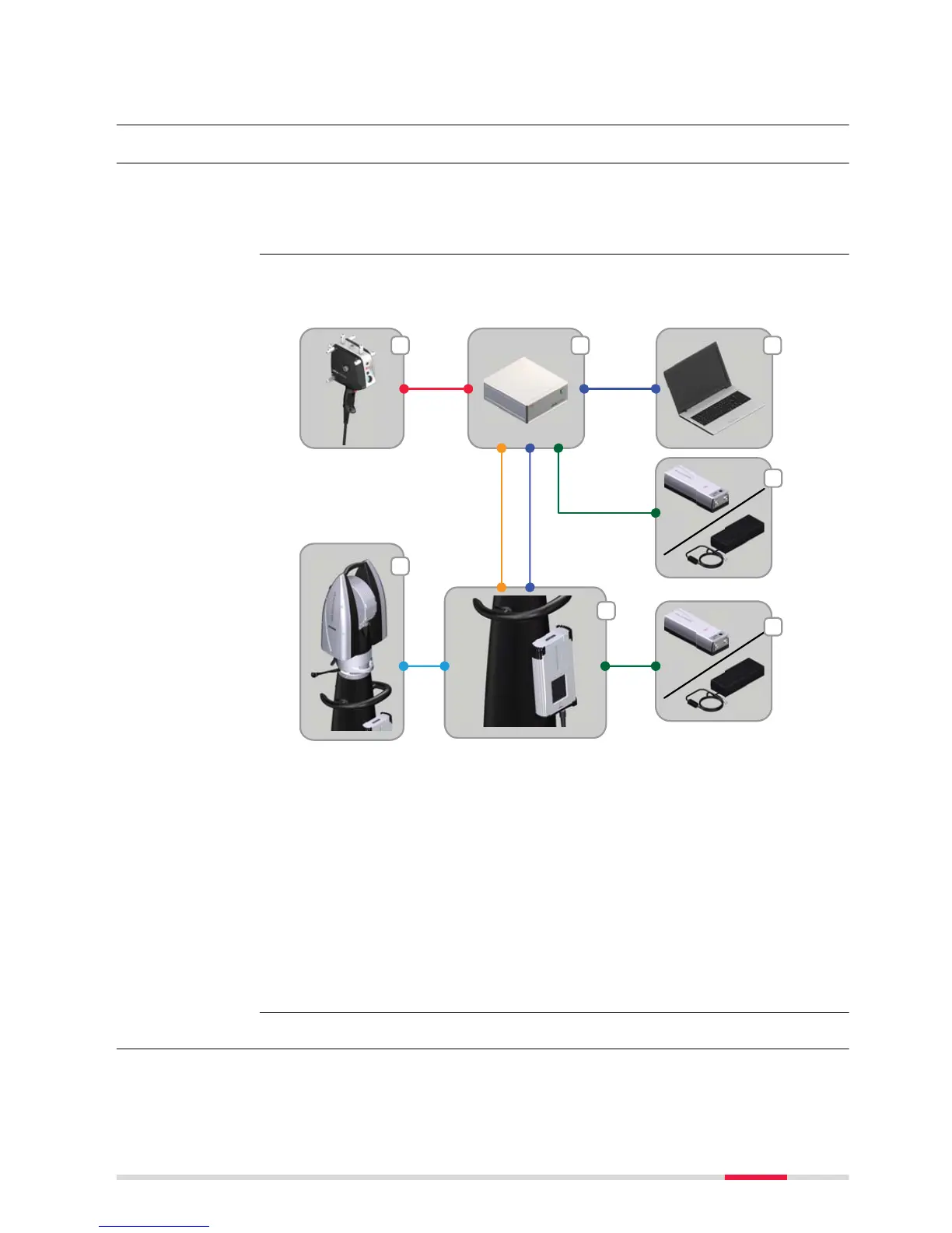
The following illustration shows the correct cabling to connect the T‑Scan sys-
tem components.
a T‑Scan 5
b T‑Scan controller
c Application computer
d Absolute Tracker (AT)
e AT‑Controller
f Battery or power supply
g Scanner cable (connector type: 19 pin LEMO)
h Trigger/probe cable (connector type: 16 pin LEMO)
i Sensor cable (connector type: 8 pin LEMO)
j LAN cable CAT6 (connector type: RJ45/RJ45)
k Power cable to power T‑Scan controller or AT‑Controller
4.2 Measurement Strategy
The inside temperature of the T‑Scan sensor increases during operation, due
to the warming of electronic components inside. This warming is taken into
account for the sensor calibration.
General
Cabling of T‑Scan
system compo-
nents
Warm-up time for
T‑Scan sensor
Operation 25
 Loading...