Page 10
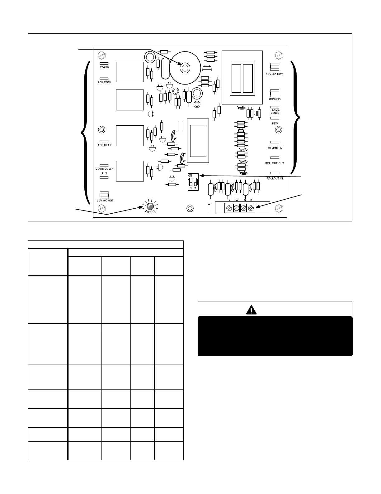
RAM CONTROL (A3)
FIGURE 5
LINE VOLTAGE
TERMINAL
CONNECTIONS
24VAC VOLT
TERMINAL
CONNECTIONS
THERMOSTAT
CONNECTIONS
DIAGNOSTIC
LED
See Table 2 for
Terminal Func-
tions
See Table 2 for
Terminal Func-
tions
FAN-OFF TIMING
SWITCHES
SPARK OUTPUT
TABLE 1
Furnace Control A3 Limit Response During Operation
Response
Condition
Combustion
Air
Blower
Gas
Valve
Supply
Air
Blower
Diagnostic
LED
Loss of Flame
Sensed Before
End of 45 sec-
ond Blower On
Delay
(3 or Fewer
Trials
for Ignition)
On
On
(Spark
Starts
Within 0.8
seconds)
On Fast Flash
Loss of Flame
Sensed After
45 second
Blower On
Delay (3 or
Fewer Trials
for Ignition)
On
Off Then
On With
Spark
After Pre-
Purge
On Fast Flash
Loss of Flame
Sensed (More
Than 3 Trials
for Ignition)
Off Off Off 2 Flashes
Flame Sensed
Without
Demand
On Off On 5 Flashes
Primary or Sec-
ondary Limit
Open
On Off On 4 Flashes
Rollout Switch
Open
On Off On 4 Flashes
Combustion Air
Prove Switch
Open
On Off On 3 Flashes
When flame is sensed, the indoor blower starts after a 45
second delay. Gas valve remains open and blower contin-
ues to run until demand stops, flame sensor senses loss of
flame, a limit opens or the prove switch opens. If any of
these events occur during a thermostat demand, the gas
valve closes and the diagnostic LED registers the error
condition (table 1).
Blower Control and Timings
DANGER
Electrical Shock Hazard.
This control contains field adjustable switches
and also contains line voltage. Make sure power
is disconnected before making any field adjust-
ments or performing any service procedure.
NOTEIf fan off" time is set too low, residual heat in
heat exchanger may cause primary limit S10 to trip re-
sulting in frequent cycling of blower. If this occurs, ad-
just blower to longer time setting.
Fan ON" timing (time that the burners operate before the
supply air blower starts) is fixed at 45 seconds and cannot
be adjusted.
 Loading...


