Page 11
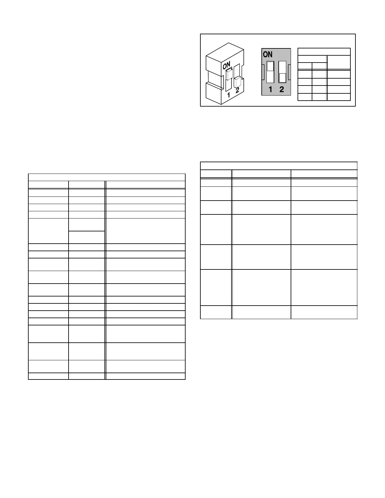
Fan OFF" timings (time that the blower operates after a
heating or cooling demand has been satisfied) are de-
termined by the arrangement of switches on the furnace
control board. See figure 5. To adjust fan off " timings,
gently reposition the switches to a new timing position.
Figure 6 shows the various fan off" timings and how
switches should be positioned. 80MGF−1, −2, −3, −4 and −6
units are shipped with a factory fan off" setting of 180 sec-
onds. 80MGF−5 and −7 units are shipped with factory "off"
setting of 60 seconds. Fan off" time will affect comfort and
efficiency and is adjustable to satisfy individual applica-
tions. The fan off" timing is initiated after a heating or cool-
ing demand but not after a blower demand (that is, when
indoor thermostat switch is changed from ON to AUTO
and heating/cooling demand is not present, the blower
stops immediately).
TABLE 2
FURNACE CONTROL A3 TERMINAL DESIGNATIONS
Terminal Type Function
Y Screw Strip Cooling Demand
G Screw Strip Blower Demand
R Screw Strip 24VAC to Thermostat
W Screw Strip Heating Demand
Early Units
1/4" Spade
Later Units
Screw Strip
ommon
120VAC HOT 1/4" Spade Line Voltage In
AUX 1/4" Spade Line Voltage Out (Switched)
CMB BLWR 1/4" Spade
Switched 120VAC to
Combustion Air Blower
ACB HEAT 1/4" Spade
Switched 120VAC to
Blower Heating Tap
ACB COOL 1/4" Spade
Switched 120VAC to Blower
Cooling Tap
VALVE 1/4" Spade 24VAC to Gas Valve
24VAC HOT 1/4" Spade 24VAC In From Transformer
GROUND 1/4" Spade To Cabinet Ground
FLAME SENSE 1/4" Spade Flame Microamp Sensing
PSW 1/4" Spade
24VAC In From Pressure Switch
Switch Open: Prohibits Ignition
Switch Closed: Allows Ignition
HI LIMIT IN 1/4" Spade
24VAC In From Limits
Limit Open: Closes Gas Valve
Limits Closed: Allows Ignition
HI LIMIT OUT 1/4" Spade
24VAC to Limit Train
and Pressure Switch
ROLLOUT IN 1/4" Spade 24VAC In From Rollout Switches
FIGURE 6
FAN-OFF TIME ADJUSTMENT SWITCHES
LOCATED ON FURNACE CONTROL (A3)
Fan-Off Timings
Switch
12
Timing
Seconds
Off
OnOff
Off
OffOn
On On
120
90
180
240
Diagnostic LED
The furnace control is equipped with a diagnostic LED
used for troubleshooting the unit and the control. LED
functions are shown in table 3.
TABLE 3
Furnace Control A3 Diagnostic LED
LED State Meaning Remedy
Steady On Control Failure Replace Control
Slow Flash
Normal Operation and
No Call For Heat
- - - -
Fast Flash
Normal Operation with
Call For Heat
- - - -
Two
Flashes
Control Lockout
Failed to Sense or Sustain
Flame. Check Gas Valve,
Burners, Spark Electrode
and Wire, Flame Sensor.
Replace Control If All OK.
Three
Flashes
Pressure Switch Open
Failed to Prove Combus-
tion Blower Operation or
Blocked Vent. Repair or
Replace as Necessary.
Four
Flashes
Open Limit
Check Primary Limit, Rollout
Switches and Secondary
Limits. Find source of Over-
temperature. If all OK, Reset
or Replace Limits as Neces-
sary.
Five
Flashes
Flame Sensed and Gas
Valve Not Energized.
Check Gas Valve. If OK,
Check Flame Sensor.
 Loading...


