Page 12
4− EGC Control (A3)
Some early model 80MGF units are equipped with an inte-
grated ignition/blower control (EGC−1 or EGC−2) which con-
trols ignition, safety circuits, blower operation, fan off timing,
and allows for thermostat connection and troubleshoot-
ing. The EGC is a printed circuit board which is divided
into two sections, 120 and 24VAC. Line voltage comes
into the board on the 120VAC side. See figure 8. Terminal
designations are listed in tables 5 and 6.
Ignition Control
80MGF units use the EGC direct spark integrated igni-
tion control. The EGC controls and monitors the entire
sequence of operation. On a call for heat from the ther-
mostat the control monitors the combustion air blower
pressure switch. The control will not begin the heating
cycle if the pressure switch is closed (by-passed). Once
the pressure switch is determined to be open, the combus-
tion air blower is energized. When the differential in pres-
sure across the pressure switch is great enough, the pres-
sure switch closes and a 15 second pre-purge period
begins. After the pre-purge period, the gas valve will open
and ignition (spark) will be attempted for 10 seconds. After
ignition, the control initiates a ten second flame stabiliza-
tion period. The flame stabilization period allows the
burners to heat up and the flame to stabilize. Once flame
is established, the control will constantly monitor the burner
flame using flame rectification. Flame failure response time is
0.8 seconds.
If the initial attempt for ignition fails, the sequence is re-
peated up to five times. After the fifth trial, the control goes into
Watchguard"*. During watchguard mode, the entire unit will
be de-energized for one hour. After one hour the control will
repeat the ignition sequence. Watchguard may be manually
reset by breaking and remaking thermostat demand.
*NOTE−If flame is established beyond the 10 second flame
stabilization period then lost, the control resets for five more
ignition trials. The control can be reset five times during one
unsatisfied thermostat demand, providing a maximum
of 25 trials for ignition.
Safety Circuits
During the entire heating demand the control monitors the
safety circuits. If the primary or secondary heating limits
open, the control de-energizes the main gas valve and
combustion air blower while the indoor blower remains en-
ergized. When the limit automatically resets, the ignition se-
quence also resets. If either of the limits trip five consecu-
tive times during one unsatisfied thermostat demand, the
control will go into watchguard for one hour.
The control monitors main valve voltage. If voltage is sensed
when no voltage should be present, the control de-energizes
the combustion air blower which terminates voltage to the
valve. The system goes into hard lock-out which is reset only
by removing power to the unit.
If flame is sensed when no flame should be present, the con-
trol will energize the combustion and indoor blowers. The
unit will remain locked in this sequence until the flame is no
longer sensed or the main power is turned off to reset the
control.
DANGER
Shock hazard. Avoid personal injury. Make sure to
disconnect power before changing fan off" timing.
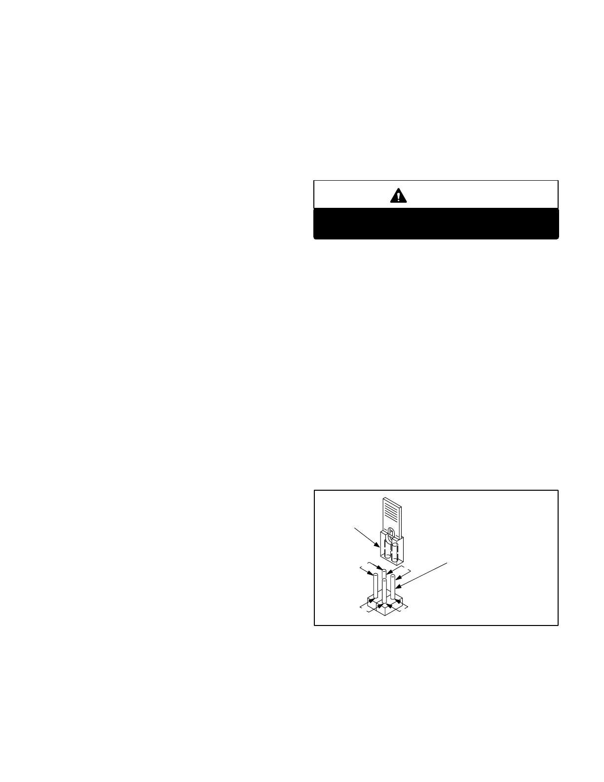
Blower Operation / Fan Off Timings
Fan off" timing (time that the blower operates after the heat
demand has been satisfied) can be adjusted by moving the
jumper on the EGC blower control board. Figure 7 shows
the various fan off" timings and how jumper should be posi-
tioned. To adjust fan off " timing, gently disconnect jumper
and reposition across pins corresponding with new timing.
Unit is shipped with a factory fan off" setting of 180 seconds.
Fan on" time is factory set at 45 seconds following the
opening of the main gas valve and is not adjustable.
Fan off" time will affect comfort and efficiency and is ad-
justable to satisfy individual applications. The fan off" tim-
ing is initiated after a heating demand but not after a cool-
ing demand.
NOTEIf fan off" time is set too low, residual heat in
heat exchanger may cause primary limit S10 to trip, re-
sulting in frequent cycling of blower. If this occurs, adjust
blower to longer fan off" time setting.
FIGURE 7
FAN-OFF TIME ADJUSTMENT
180
60
120 90
To adjust fan-off timing:
Remove jumper from EGC and select one
of the other pin combinations to achieve
the desired time.
TIMING
JUMPER
TIMING PINS
(seconds)
Leave jumper off for
240 second fan-off timing.
Thermostat Connection
Thermostat wires are connected to the terminal strip
found on the EGC control board.
 Loading...


