0906-E
23
CONDENSING FANS CONTROL
Function
Maintain the condensing pressure as stable and as low as possible in order to increase the unit
performances, while avoiding excessive cycling.
Description
Identical to the complete machine control logic, the CLIMATIC
TM
50’s aim is to reach and hold the high
pressure set point. However the fan control includes a dead zone ensuring a greater stability to the High
Pressure and avoiding starting and stopping the fans too frequently.
Can be adjusted using menus
3611 = High pressure control set point in bars (relative pressure)
3612 = Reactivity
Operation
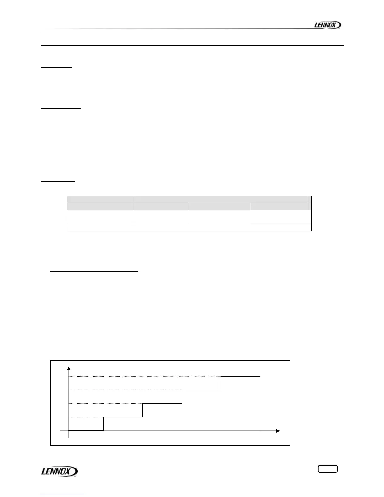
On a unit with N fans per circuit, the number of stages follows the table hereunder:
Number of Stages
Model PV with PWM PV GV
WA/RA
STD/HE/SLN
1 0 N-1
WA LN 1 N-1 0
Where: PV: Low speed Fan Operation
GV: High Speed Fan Operation
PWM: Pulse Width modulation (only on PV)
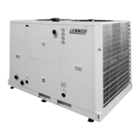
CASE 1 Unit without PV or PWM
The Ventilation Factor “V.F.” is calculated using the evolution of High Pressure (measured using the HP
sensor) and the rate at which it is moving away or towards the High Pressure Set Point (3611). See diagram
page 12.
It also includes a dead zone of 5 bars (4 bars if the unit has glycol and water set point <0°C) and a sampling
time constant of 15 seconds.
As for capacity control, the reactivity will fasten or slow down the VF evolution
Example: Unit with 3 fans, one circuit and HP set point 3611 is set to 15 bars
# Pressure > 15 bars ! V.F. increasing
# 10 bars < Pressure < 15 bars ! V.F. unchanged
# Pressure < 10 bars ! V.F. decreasing
25%
50%
100%
75%
Ventilation Facto