3DJH
4. BCC Blower Control (A15)
-1 Through -4 Models
G23(X)-1, -2, -3 and -4 model units utilize the BCC blower
control manufactured by Heatcraft. See figure 10. The BCC
is a printed circuit board which controls the supply air blow-
er and monitors primary limit and gas valve operation. The
BCC is equipped with a jumper for electronic (isolation
relay) or electro-mechanical thermostat selection.The con-
trolhas a non-adjustable, factory preset fan “on” timing. Fan
“off” timing is adjustable. The board is divided into two sec-
tions, 120 and 24VAC. Line voltage comes into the board
on the 120VAC side. See table 1 for terminal designations.
Fan Timings
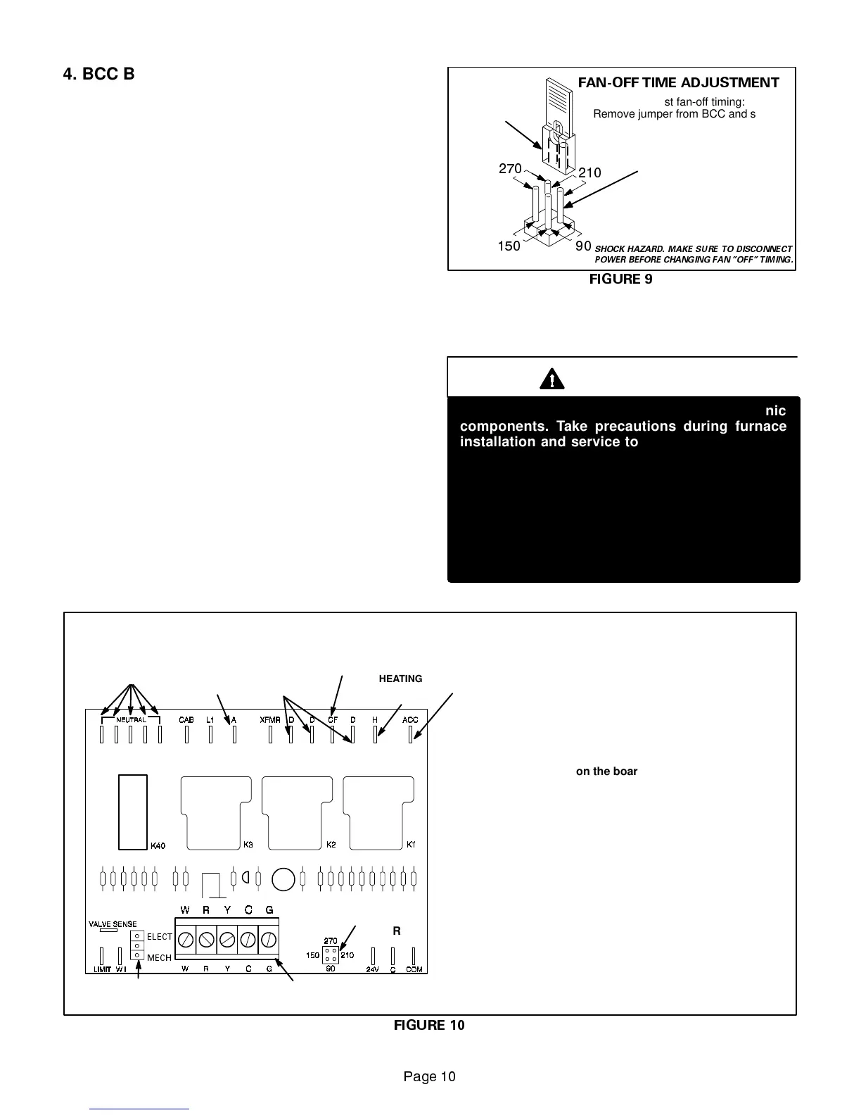
Fan “off” timing (time that the blower operates after the heat
demand has been satisfied) is determined by the arrange-
ment of a jumper across pins on the BCC blower control
board. See figure 9. To adjust fan“off” timing, gently discon-
nect jumper and reposition across pins corresponding with
new timing. Fan “on” time is factory set at 45 seconds andis
not adjustable.
NOTE—If fan “off” time is set too low, residual heat in
heat exchanger may cause primary limit S10 to trip re-
sulting in frequent cycling of blower. If this occurs, ad-
just blower to longer time setting.
Figure 9 shows the various fan “off” timings and how jumper
should be positioned. Unit is shipped with a factory fan “off”
setting of 90 seconds. Fan “off” time will affect comfort and
efficiency and is adjustable to satisfy individual applications.
The fan “off” timing is initiated after a heating demand but not
after a blower or cooling demand (that is, when indoor ther-
mostat switch is changed from ON to AUTO and heating/
cooling demand is not present, the blower stops immediate-
ly).
FIGURE 9
FAN-OFF TIME ADJUSTMENT
To adjust fan-off timing:
Remove jumper from BCC and select
one of the other pin combinations to
achieve the desired time.
TIMING
JUMPER
TIMING PINS
(seconds)
Leave jumper off for
330 second fan-off timing.
SHOCK HAZARD. MAKE SURE TO DISCONNECT
POWER BEFORE CHANGING FAN OFF TIMING.
CAUTION
Electrostatic discharge can affect electronic
components. Take precautions during furnace
installation and service to protect the furnace’s
electroniccontrols.Precautionswillhelpto avoid
control exposure to electrostatic discharge by
putting the furnace, the control and the techni-
cian at the same electrostatic potential. Neutral-
ize electrostatic charge by touching hand and all
tools on an unpainted unit surface, such as the
gas valve or blower deck, before performing any
service procedure.
ELECTROSTATIC DISCHARGE (ESD)
Precautions and Procedures
G23(X)-1, -2 ,-3 and -4 MODELS
BLOWER CONTROL - BCC
(A15)
FIGURE 10
NEUTRAL
TERMINALS
ACCESSORY
TERMINAL
THERMOSTAT TERMINAL STRIP
(DETACHABLE ON EARLY BOARDS ONLY))
BLOWER TIME
ADJUSTMENT
JUMPER
HEATING
SPEED TAP
TERMINAL
COOLING
SPEED TAP
TERMINAL
DUMMY
TERMINALS
CONTINUOUS FAN
TERMINAL
MECH
ELECT
THERMOSTAT JUMPER
(Electronic or Mechanical)
Heat Anticipator Settings
Beginning with the BCC3-2 series, a 3 pin jumper
has been installed on the board next to the remov-
able 24V terminal strip to account for both program-
mable and electromechanical thermostat usage in
the field. For electromechanical thermostat, position
the jumper over the middle and bottom pin labeled
”MECH.” Set the heat anticipator setting to 0.65
amps for Honeywell valves or 0.50 amps for White
Rodgers valves. For programmable (electronic) ther-
mostats, position the jumper over the middle and
top pin labeled ”ELECT.” Set the heat anticipator
setting to 0.1 amps.
 Loading...