3DJH
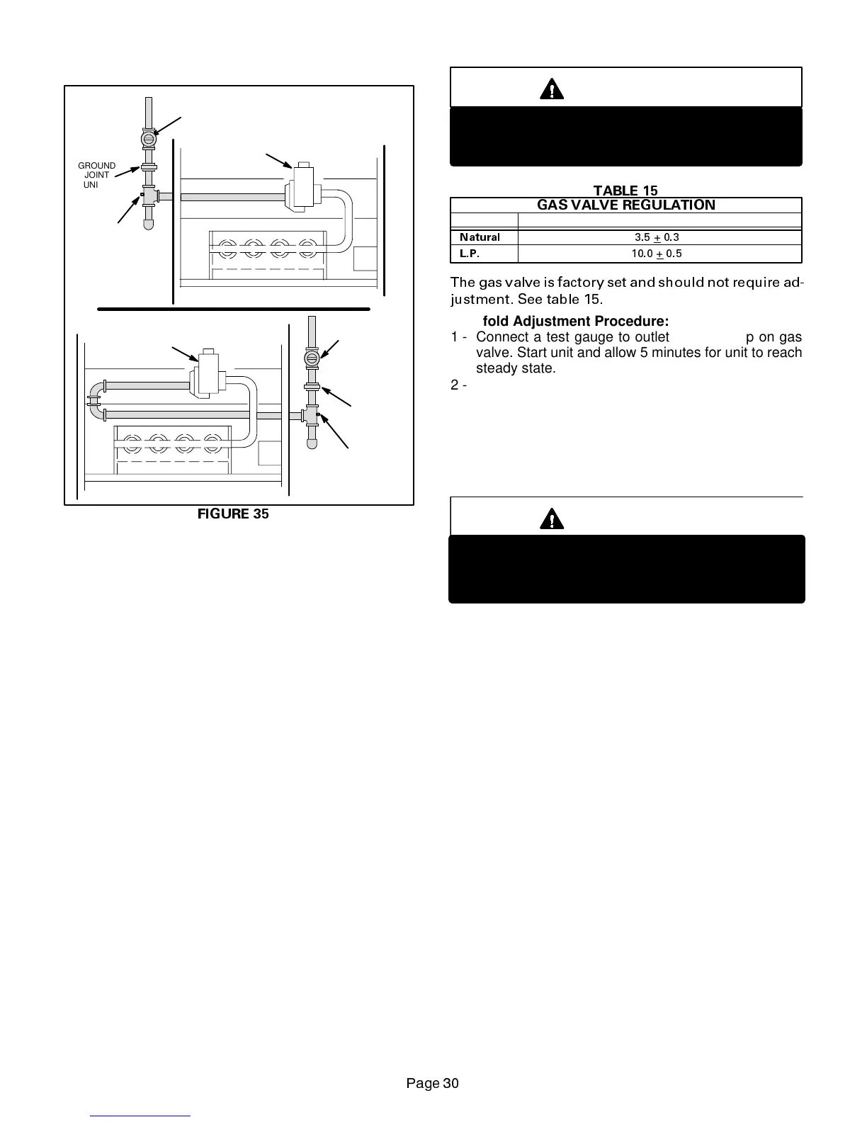
FIGURE 35
GROUND
JOINT
UNION
LEFT SIDE PIPING
(STANDARD)
RIGHT SIDE PIPING
AUTOMATIC
GAS VALVE
MANUAL
MAIN SHUT-OFF
VALVE
1/8” NPT
PLUGGED
TAP
GROUND
JOINT
UNION
MANUAL
MAIN SHUT-OFF
VALVE
1/8” NPT
PLUGGED
TAP
AUTOMATIC
GAS VALVE
When checkin
pipin
connections for
as leaks, use pre-
ferred means. Kitchen deter
ents can cause harmful corro-
sion on various metals used in
as pipin
. Use of a specialt
Gas Leak Detector is stron
l
recommended. It is available
throu
h Lennox under part number 31B2001. See Corp.
8411-L10, for further details.
Do not use matches, candles, flame or an
other source of
i
nition to check for
as leaks.
D-Check Manifold Pressure
After line pressurehas been checked and ad
usted, check
manifold pressure. Move pressure
au
etooutletpres-
sure tap located on unit
as valve
GV1
. Checks of man-
ifold pressure are made as verification of proper re
ulator
ad
ustment. Manifold pressure for the G23
X
can be mea-
sured at an
time the
as valve is open and is suppl
in
as
to the unit. Normal manifold pressure for natural
as units is
3.5 in. w.c. For LP
as the correct manifold pressure is 10.0
in. w.c.
IMPORTANT
For safety, connect a shut-off valve between the
manometer and the gas tap to permit shut off of
gas pressure to the manometer.
Operating Pressure (outlet) in. W.C.
TABLE 15
GAS VALVE REGULATION
3.5 + 0.3
Natural
L.P.
10.0 +
0.5
Unit (Fuel)
The gas valve is factory set and should not require ad-
justment. See table 15.
Manifold Adjustment Procedure:
1 - Connect a test gauge to outlet pressure tap on gas
valve. Start unit and allow 5 minutes for unit to reach
steady state.
2 - While waiting for the unit to stabilize, notice the flame.
Flame should be stable and should not lift from burner.
Natural gas should burn blue. L.P. gas should burn
mostly blue with some orange streaks.
3 - After allowing unit to stabilize for 5 minutes, record
manifold pressure and compare to values given in
table 15.
IMPORTANT
For safety, shut unit off and remove manometer
as soon as an accurate reading has been ob-
tained. Take care to replace pressure tap plug.
E-Testing Gas Supply Pressure
When testing supply gas pressure, connect test gauge to
inlet pressure tap (field provided). See figure 35. Check
gas line pressure with unit firing at maximum rate. Low
pressure may result in erratic operation or underfire. High
pressure can result in permanent damage to gas valve or
overfire. For natural gas units, operating pressure at unit
gasconnectionmustbe between4.5” W.C.and 13.0”W.C.
For L.P. gas units, operating pressure at unit gas connec-
tion must be between 10.5” W.C. and 13.0” W.C.
On multiple unit installations, each unit should be checked
separately, with and without units operating. Supply pres-
sure must fall within range listed in previous paragraph.
 Loading...