3DJH
127( 7KH *; IXUQDFH FRQWDLQ
V HOHFWURQLF FRP
SRQHQWV WKDW DUH SRODULW\ VHQVLWLYH 0DNH VXUH WKDW WKH
IXUQDFH LV ZLUHG FRUUHFWO\ DQG LV SURSHUO\ JURXQGHG
DANGER
Shock hazard.
Disconnect power before servicing. Control is not
field repairable. If control is inoperable, simply
replace entire control.
Can cause injury or death. Unsafe operation will
result if repair is attempted.
I- SureLight Ignition System A3
(-5 and -6 models)
All G23(X)-5 and -6 model units are equipped with the
Lennox SureLight ignition system. The system consists
of ignition control board (figure 21 with control terminal
designations intable5) and ignitor (figures 18, 19 and 20.
The board and ignitor work in combination to ensure fur-
nace ignition and ignitor durability. The SureLight inte-
grated board controls all major furnace operations. The
board also features two LED lights for troubleshooting
and two accessory terminals rated at (4) four amps. See
table 6 for troubleshooting diagnostic codes. Table 7 and
8 show jack plug terminal designations. Units equipped
withtheSureLightboardcanbeusedwitheitherelectron-
ic or electro-mechanical thermostats without modifica-
tion. The SureLight ignitor is made of durable silicon-ni-
tride. Ignitor longevity is also enhanced by voltage ramp-
ing by the control board. The board finds the lowest igni-
tor temperature which will successfully light the burner,
thus increasing the life of the ignitor.
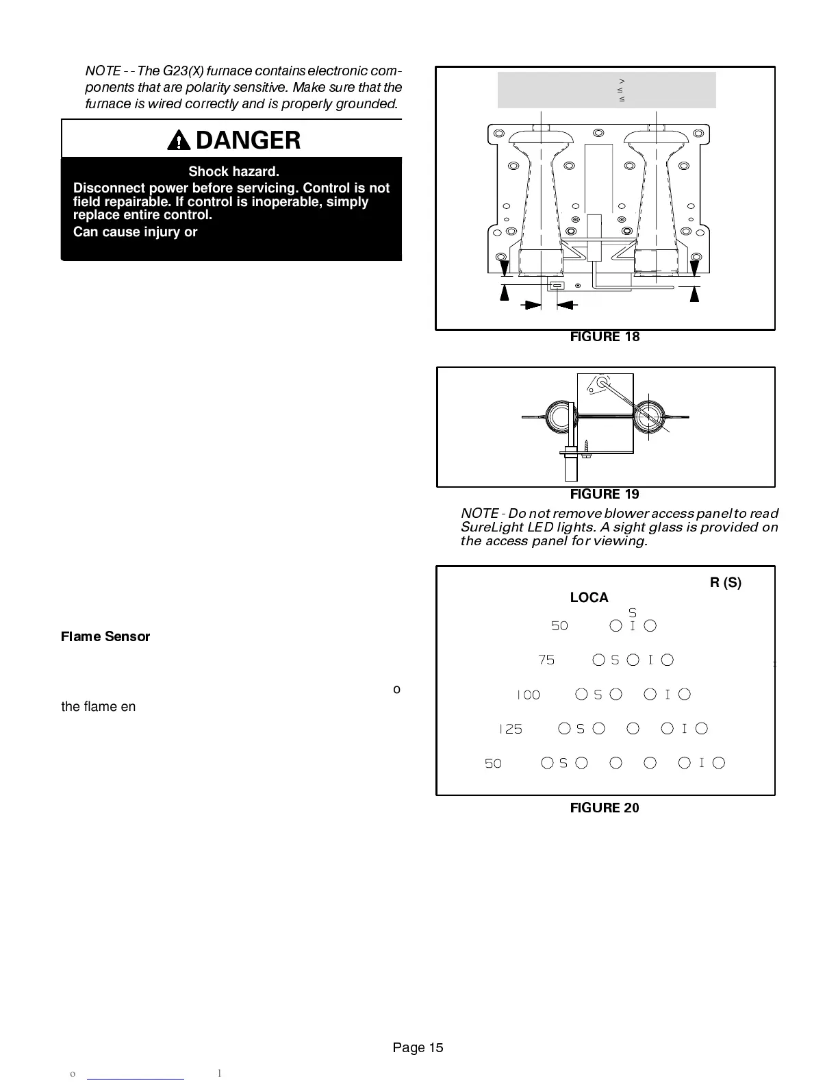
)ODPH 6HQVRU
A flame sensor is located on the left side of the burner sup-
port. See figures 18, 19 and 20. The sensor is mounted on
a bracket in the burner support and the tip protrudes into
the flame envelope of the left-most burner. The sensor is
fastened to burner supports and can be removed for ser-
vice without removing any part of the burners. During op-
eration, flame is sensed by current passed through the
flame and sensingelectrode. The SureLight controlallows
the gas valve to remain open as long as flame signal is
sensed.
FIGURE 18
NORMAL FLAME SIGNAL
0.7 MICROAMPS
LOW FLAME SIGNAL
$
0.7 MICROAMPS
MINIMUM FLAME SIGNAL
$
0.15 MICROAMPS
3/8”
1/4”
19/64”
SENSOR
IGNITOR
FIGURE 19
IGNITOR
SENSOR
NOTE - Do notremove blower access panel to read
SureLight LED lights. A sight glass is provided on
the access panel for viewing.
FIGURE 20
SURELIGHT IGNITOR (I) AND SENSOR (S)
LOCATION
 Loading...