3DJH
I-UNIT COMPONENTS (Figures 1 and 2)
G23(X) unit components are shown in figures 1and 2. The
gas valve, ignitioncontrolandburnerscanbeaccessed by
removing the burner access panel. The blower, blower
control and SureLight control can be accessed by remov-
ing the blower access door.
G23(X) units are factory equipped with bottom and side return
air panels in place. The panels are designed to be field re-
moved as required for bottom air return or side air return.
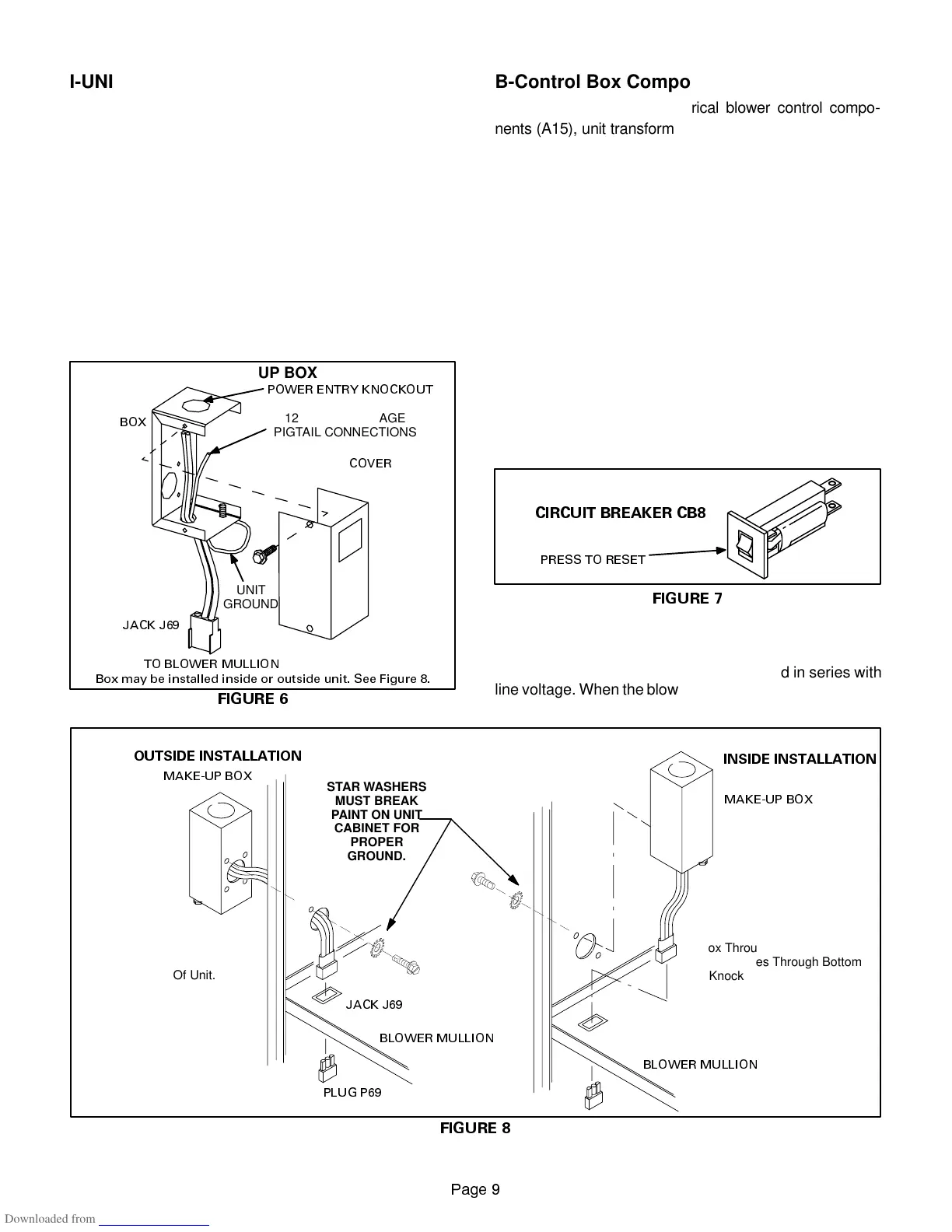
A-Make-Up Box (Figure 6)
Thelinevoltagemake-upboxisshowninfigure6.Thebox
may be installed inside or outside the unit and may be
installed on the unit left or right side (figure 8).
FIGURE 6
MAKE-UP BOX
BOX
COVER
JACK J69
TO BLOWER MULLION
POWER ENTRY KNOCKOUT
120V LINE VOLTAGE
PIGTAIL CONNECTIONS
UNIT
GROUND
Box may be installed inside or outside unit. See Figure 8.
B-Control Box Components (Figures 4 & 5)
SureLight control (A3), Electrical blower control compo-
nents (A15), unit transformer (T1) and 24V circuit breaker
(CB8) are located in the control box. In addition, a door in-
terlock switch(S51)islocatedinthecontrolbox. Jackplugs
allow the control box to be easily removed for blower ser-
vice.
1. Control Transformer (T1)
A transformer located in the control box provides power to
the low voltage 24volt section of the unit. Transformers on
all models are rated 40VA with a 120V primary and a 24V
secondary.
2. Circuit Breaker (CB8)
A 24V circuit breaker is also located in the control box.
The switch provides overcurrent protection to the
transformer (T1). The breaker is rated 3A at 32V. If the
currentexceedsthislimitthebreakerwilltripandallunit
operation will shutdown. The breaker can be manually
reset by pressing the button on the face. See figure 7.
FIGURE 7
CIRCUIT BREAKER CB8
PRESS TO RESET
3.Door Interlock Switch (S51)
A door interlock switch rated 14A at 125VAC is located on
the blower access door. The switch is wired in series with
line voltage. When the blower door is removed the unit will
shut down.
FIGURE 8
MAKE-UP BOX INSTALLATION
MAKE-UP BOX
MAKE-UP BOX
UNIT
CABINET
Box may be installed inside or outside cabinet and may
be installed on left side or right side of cabinet
JACK J69
PLUG P69
BLOWER MULLION
BLOWER MULLION
OUTSIDE INSTALLATION
INSIDE INSTALLATION
Line Voltage Enters Make-Up
Box Through Side Of Unit and
J69 Passes Through Bottom
Knockout in Make-Up Box.
Line Voltage Enters Through
Knockout In Make-Up Box. J69
Passes Through Side Knockout
Into Side Of Unit.
STAR WASHERS
MUST BREAK
PAINT ON UNIT
CABINET FOR
PROPER
GROUND.
 Loading...