FIGURE 36
TRANSDUCER
(PART #78H5401)
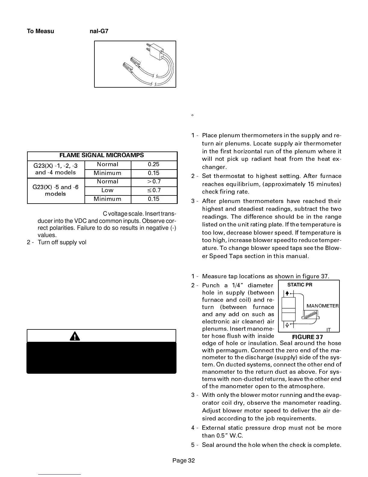
FIGURE 37
STATIC PRESSURE
TEST
MANOMETER
G23(X) UNIT
3DJH
To Measure Flame Signal-G776 Ignition Control:
A transducer (Part
#78H5401 available
from Lennox Repair
Parts) is required to
measure flame
signal. See figure 36.
The transducer converts
microamps to volts on a
1:1 conversion. If the flame signal should read 0.15-0.25
microamps, a reading of 0.15-0.25 volts should be read on
the meter. See table 19 for correct microamp reading.
A digital readout meter must be used. The transducer plugs
into most meters.
TABLE 19
FLAME SIGNAL MICROAMPS
G23(X) -1, -2, -3
Normal 0.25
,
,
and -4 models
Minimum 0.15
Normal
0.7
G23(X) -5 and -6
Low
$
0.7
Minimum 0.15
1 - Setthevolt meter tothe DCvoltagescale.Inserttrans-
ducer into the VDC and common inputs. Observe cor-
rect polarities. Failure to do so results in negative (-)
values.
2 - Turn off supply voltage to control.
3 - Disconnect flame sensor lead from terminal of ignition
control.
4 - Connect (+) lead of transducer to ignition control sen-
sor connection.
5 - Connect (-) lead of the transducer to sensor wire.
6 - Turn supply voltage on and close thermostat contacts
to cycle system.
7 - When unit lights read voltage on meter display. Re-
member 1 DC volt = 1 DC microamp. See table 19 for
correct microamp reading.
WARNING
Fire and explosion hazard.
These instructions MUST be followed exactly.
Can causea fire orexplosion resulting in property
damage, personal injury or loss of life.
Flame signal may rise above 0.5 microamps for the first
few seconds after ignition and then level off within the
range.
V-TYPICAL OPERATING CHARACTERISTICS
A-Blower Operation and Adjustment
NOTE- The following is a generalized procedure and
does not apply to all thermostat controls.
1 - Blower operation is dependent on thermostat control
system.
2 - Generally, blower operation is set at thermostat sub-
base fan switch. With fan switch in ON position, blower
operates continuously. With fan switch in AUTO posi-
tion, blower cycles with demand or runs continuously
while heating or cooling circuit cycles.
3 - In all cases, blower and entire unit will be off when the
system switch is in OFF position.
B-Temperature Rise
Temperature rise for G23(X) units depends on unit input,
blower speed, blower horsepower and static pressure as
marked onthe unit rating plate. The blower speed must be
set for unitoperationwithin therangeof “AIRTEMP. RISE
q
F” listed on the unit rating plate.
To Measure Temperature Rise:
1 - Place plenum thermometers in the supply and re-
turn air plenums. Locate supply air thermometer
in the first horizontal run of the plenum where it
will not pick up radiant heat from the heat ex-
changer.
2 - Set thermostat to highest setting. After furnace
reaches equilibrium, (approximately 15 minutes)
check firing rate.
3 - After plenum thermometers have reached their
highest and steadiest readings, subtract the two
readings. The difference should be in the range
listed on the unit rating plate. If the temperature is
too low, decrease blower speed. If temperature is
too high, increase blower speed to reduce temper-
ature. To change blower speed taps see the Blow-
er Speed Taps section in this manual.
C-External Static Pressure
1 - Measure tap locations as shown in figure 37.
2 - Punch a 1/4 diameter
hole in supply (between
furnace and coil) and re-
turn (between furnace
and any add on such as
electronic air cleaner) air
plenums. Insert manome-
ter hose flush with inside
edge of hole or insulation. Seal around the hose
with permagum. Connect the zero end of the ma-
nometer to the discharge (supply) side of the sys-
tem. On ducted systems, connect the other end of
manometer to the return duct as above. For sys-
tems with non-ducted returns, leave the other end
of the manometer open to the atmosphere.
3 - With only the blower motor running and the evap-
orator coil dry, observe the manometer reading.
Adjust blower motor speed to deliver the air de-
sired according to the job requirements.
4 - External static pressure drop must not be more
than 0.5 W.C.
5 - Seal around the hole when the check is complete.
 Loading...