3DJH
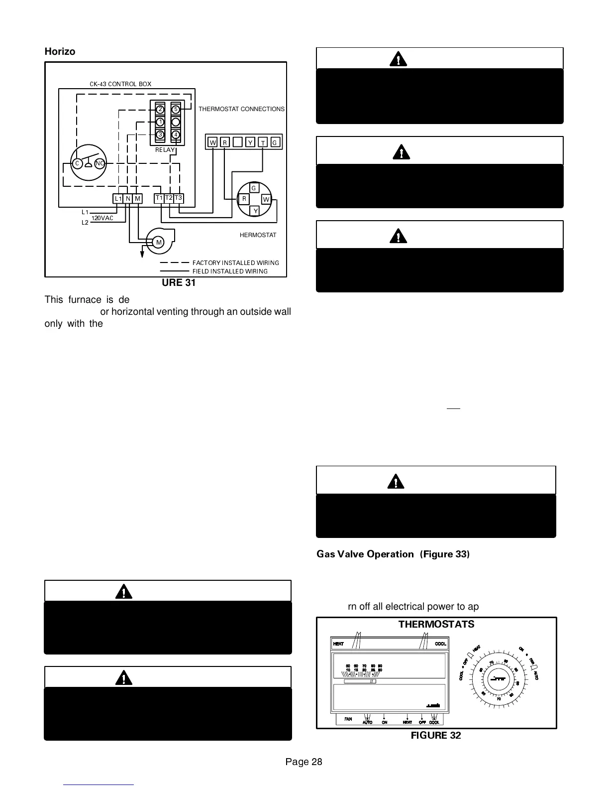
Horizontal Venting
SIDE WALL VENTING KIT WIRING
C
L1
L2
120VAC
M
L1 MN
T1 T2 T3
WR Y G
W
G
R
Y
24 VAC
THERMOSTAT
THERMOSTAT CONNECTIONS
TERMINAL IN FURNACE
JUNCTION BOX
RELAY
CK-43 CONTROL BOX
PRESSURE
SWITCH
SWG
POWER
VENTER
MOTOR
FIGURE 31
T
FIELD INSTALLED WIRING
FACTORY INSTALLED WIRING
NO
2
1
3
5
4
This furnace is design certified by the American Gas
Association for horizontal venting through an outside wall
only with the use of a Field Controls Company Model
SWG-4L side wall venting kit available from Lennox Deal-
er Service Center. No other Field brand venting kit or any
other manufacturer’s venting kit is acceptable. Horizontal
venting of this furnace without the use of the above stated
kit is prohibited. See figure 31 for field wiring of side wall
horizontal venting kit.
When horizontally vented, minimum clearance for ter-
mination from electric meters, gas meters, regulators and
relief equipment is 4 ft. (1.2m).
III-START-UP
A-Preliminary and Seasonal Checks
1 - Inspect electrical wiring, both field and factory installed
for loose connections. Tighten as required.
2 - Check voltage at disconnect switch. Voltage must be
withinrangelistedon thenameplate.If not, consultthe
power company and have voltage condition corrected
before starting unit.
B-Heating Start-Up
FOR YOUR SAFETY READ BEFORE LIGHTING
WARNING
Shock and burn hazard.
G23(X)-1 through -4 model units are equipped with
an electronic spark ignition system. Do not attempt
to light manually.
WARNING
Shock and burn hazard.
G23(X)-5 and -6 model units are equipped with the
SureLight ignition system. Do not attempt to light
manually..
WARNING
Donot use thisfurnaceif anyparthas beenunder-
water. Inspect the furnace and replace any part of
the control system and any gas control which has
been under water.
CAUTION
Before attempting to perform any service or main-
tenance, turn the electrical power to unit OFF at
disconnect switch.
WARNING
If overheating occurs or if gas supply fails to shut
off, shut off the manual gas valveto the appliance
before shutting off electrical supply.
BEFORE LIGHTING smell all around the appliance area
for gas. Be sure to smell next to the floor because some
gas is heavier than air and will settle on the floor.
Use only your hand to push in or turn the gas control knob.
Never use tools. If theknob willnot push in or turn by hand,
do not try to repair it, call a qualified service technician.
Force or attempted repair may result in a fire or explosion.
G23(X) -1 through -4 model units are equipped with an inter-
mittent pilot ignition system. Do not
attempt to manually light
pilot on these furnaces. Each time thermostat calls for heat,
the pilot will be automatically lit. The pilot does not burn when
there is no call for heat.
How To Operate Gas Valve (Figure 33)
WARNING
If you do not follow these instructions exactly, a
fire or explosion may result causing property
damage, personal injury or loss of life.
Gas Valve Operation (Figure 33)
1- STOP! Read the safety information at the beginning
of this section.
2 - Set thermostat to lowest setting. See figure 32.
3 - Turn off all electrical power to appliance.
THERMOSTATS
FIGURE 32
 Loading...