Page 16
Diagnostic LED
The furnace control is equipped with a diagnostic LED
used for troubleshooting the unit and the control. LED
functions are shown in table 7.
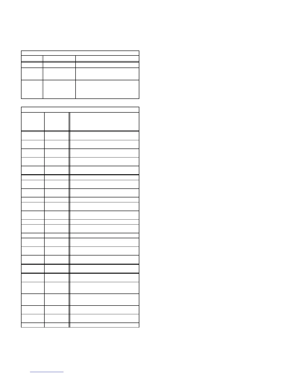
TABLE 7
Furnace Control A3 Diagnostic LED
LED State Meaning Remedy
Steady On Normal Operation - - - -
Slow Flash
(1 sec. on/
5 sec. off)
Control Retry
Period
Failed to Sense Flame. Ignition Con-
trol Will Retry
Before Locking Out.
Off
Control Failure or
Power Failure or
Hard Lockout
If Power and Gas Supply are OK, Try
Removing T’stat Demand For At Least
30 Seconds. If LED Remains Off
When Demand Is Returned, Replace
Control.
TABLE 8
BLOWER CONTROL A15 TERMINAL DESIGNATIONS
Terminal
(Designation
on Wiring
Diagram)
Type Function
Y
Detachable
Screw Strip
Cooling Demand
G
Detachable
Screw Strip
Blower Demand
R
Detachable
Screw Strip
24VAC to Thermostat
W
Detachable
Screw Strip
Heating Demand
T
Detachable
Screw Strip
24VAC Common
To Indoor Thermostat
IBN (N) 1/4" Spade 120VAC Indoor Blower Common
N1 (N) 1/4" Spade
120VAC Neutral
(L2 Line Voltage Neutral)
CABN (N) 1/4" Spade
120VAC Combustion Air Blower Com-
mon
XFMRN(N) 1/4" Spade 120VAC Transformer Common
HSIN (N) 1/4" Spade
120VAC Hot Surface Ignition
Common (Not Used)
CAB 1/4" Spade
Switched 120VAC to
Combustion Air Blower
L1 1/4" Spade 120VAC Line Voltage In
A 1/4" Spade
Switched 120VAC
to Blower Cooling Tap
XFMR 1/4" Spade 24VAC In From Transformer
D 1/4" Spade
Dummy Connection for
Unused Blower Leads
CF 1/4" Spade
Switched 120VAC to
Continuous Blower Tap
H 1/4" Spade
Switched 120VAC to
Blower Heating Tap
ACC 1/4" Spade
Switched 120VAC to Accessory (Elec-
tronic Air Cleaner, Humidifier, Etc.)
24V
(24)
1/4" Spade 24VAC Input From Transformer
LIMIT
(L)
1/4" Spade
24VAC In From Primary Limit. Limit
Open: Closes Gas Valve and Turns On
Blower Limit Closed: Allows Ignition
W 1/4" Spade
24VAC Thermostat Demand Output
Through Differential Switch to THS"
Terminal of Ignition Control
VALVE
SENSE (V)
3/16" Spade 24VAC Input From Gas Valve
T 1/4" Spade
24VAC Common From
Ignition Control and Gas Valve
COM (C) 1/4" Spade 24VAC Common To Transformer
Johnson G776 Ignition Control Operation
The information in this section is protected by a copyright issued by
Johnson Controls, Inc., and is reproduced with permission.
On a call for heat from indoor thermostat, the ignition control
energizes and ignition control LED lights (steady on). The
combustion air blower is energized. After 15 second pre-
purge period, the control simultaneously opens pilot valve
and sends spark to pilot electrode.
If pilot ignites within 85 seconds, flame sensor detects pilot
flame and signals ignition control to energize the main
valve. The main valve cannot be energized until sensor
detects pilot flame. Spark continues until pilot flame is
sensed or 85 seconds has elapsed.
When pilot flame is sensed, main valve is energized and
spark turns off. The ignition control remains in run" mode un-
til indoor thermostat is satisfied or flame lost.
If pilot flame is not sensed before the end of the 85 second trial
for ignition, the control enters the 100% shutoff mode. The
spark circuit and pilot valve de-energize and the ignition con-
trol automatically begins the 60 minute retry delay period.
During the 60 minute delay the diagnostic LED continually
flashes on for one second and off for five seconds. After the
delay period, another trial for ignition sequence starts, begin-
ning with pre-purge.
If pilot flame goes out while the indoor thermostat is calling
for heat, both main and pilot valves de-energize within 0.8
seconds and remain de-energized for five seconds. After
this delay, the spark and pilot valve energize until flame is
sensed or the 85 second trial for ignition period ends. If this
flameout" cycle repeats 16 times (pilot flame is estab-
lished and then lost), the control locks out and the LED
goes off. A new trial for ignition sequence begins after the
thermostat contacts are opened for 2 seconds and then
closed.
If flame is detected when the thermostat calls for heat, it
must extinguish within 30 seconds for normal operation. If
flame is still present after 30 seconds, the control goes into
lockout and the LED goes off.
13−Pilot, Spark Electrode, Flame Sensor
(−1 and −2 models)
Figure 18 shows the arrangement of pilot, flame sensor,
spark electrode and burners. The ignition control uses di-
rect spark to ignite the pilot. The pilot ignites the burners
and the burners cross-light. The flame sensor uses flame
rectification to sense pilot ignition. The ignition control re-
quires that pilot flame must be sensed before the main gas
valve is allowed to open. Typically, a 2 to 4 second delay
occurs between the pilot ignition and the main valve open-
ing. Figure 19 shows the gap between the tip of the elec-
trodes and the burner surface. It is important that the gap
be maintained for consistent ignition of pilot flame.
 Loading...