Page 17
FIGURE
18
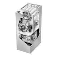
TYPICAL BURNER PILOT/ELECTRODE ORIENTATION
view looking at side of burners
FRESH AIR INTAKE
BURNER BOX
MANIFOLD
BURNERS
PILOT
HOOD
SPARK
ELECTRODE
FLAME SENSOR
GAP
Both pilot and main burner flame should be predominantly
blue and strong in appearance. Pilot flame must surround
the end of flame sensor for proper operation of pilot safety
circuit.
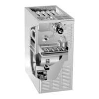
FIGURE 19
PILOT, SPARK ELECTRODE
AND FLAME SENSOR
1/8 (.125) Inch "1/32 (.031)
SPARK ELECTRODE
FLAME SENSOR
PILOT
PILOT HOOD
GAP
SPARK WIRE
SENSOR WIRE
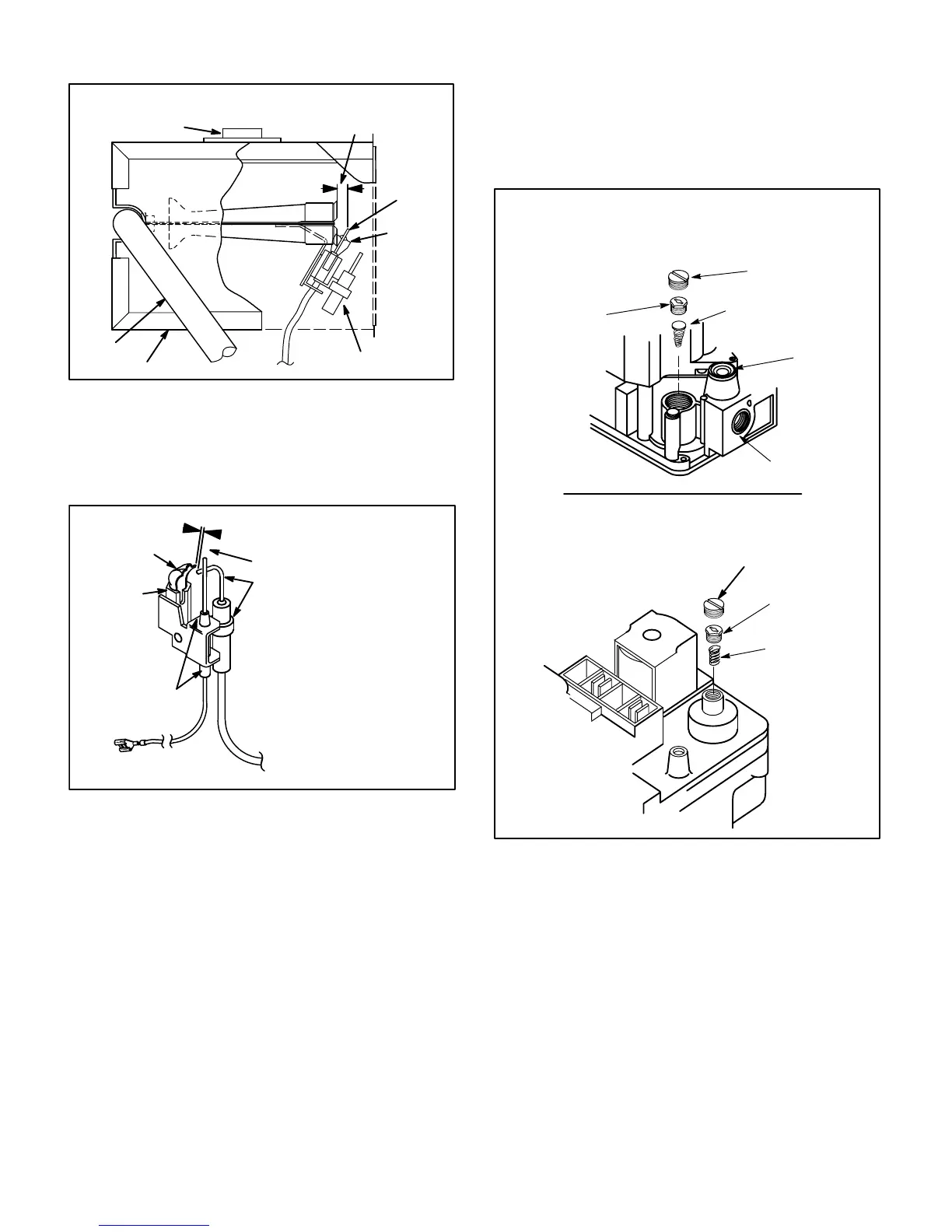
14−Gas Valve
The G26 uses a gas valve manufactured by Honeywell or
White Rodgers. See figure 20. The valve is internally re-
dundant to assure safety shut-off. If the gas valve must be
replaced, the same type valve must be used.
24VAC terminals and gas control knob are located on top of
the valve. All terminals on the gas valve are connected to
wires from the ignition control. 24V applied to the MV" termi-
nals on the Honeywell or M/C or 1/2 terminals on the White
Rodgers opens the main valve. Inlet and outlet pressure taps
are located on the valve. A regulator adjustment screw (figure
20 ) is located on the valve. Regulator cover screw must be in
place when reading manifold pressure.
An LPG changeover kit is available. The kit includes main and
pilot burner orifices (pilot orifice for −1 and −2 units only) and a
regulator conversion kit. All L.P. orifices can be identified by a
band around the orifice. Natural gas orifices do not have the
band.
INLET
PRESSURE
TAP
REGULATOR
COVER SCREW
(Black)
ADJUSTING
SCREW
(White)
SPRING Tapered End
Down (Red)
GAS INLET
PRESSURE
REGULATOR
REGULATOR
COVER SCREW
WHITE RODGERS 36E GAS VALVE
REGULATOR ADJUSTMENT SCREW
LOCATION
HONEYWELL VR8204 GAS VALVE
REGULATOR ADJUSTMENT SCREW LOCATION
ADJUSTING SCREW
(White)
SPRING
FIGURE 20
100% Sealed Combustion
The burner box is completely sealed and operates under a
negative pressure. A pressure hose is connected from the
burner box to the gas valve regulator and differential pres-
sure switch. The gas valve senses the pressure in the
burner box and changes gas valve output based on
changes in burner box pressure. The intent is to compen-
sate for different vent configurations which can greatly af-
fect the rate of the unit.
 Loading...