Do you have a question about the Lennox G26 Series and is the answer not in the manual?
| Heating Stages | Single-stage |
|---|---|
| Blower Motor | PSC (Permanent Split Capacitor) |
| Gas Valve | Single-stage |
| Vent Type | Natural Draft |
| Fuel Type | Natural Gas or Propane |
| Blower Motor Type | PSC |
| Warranty | 5-Year Limited Warranty on covered components |
| Heating Capacity | 44, 000 to 132, 000 BTU/h |
| Filter Type | Standard |
Detailed explanation of the furnace's combustion cycle, from air intake to flue exhaust.
List of optional accessories available for the G26 series furnaces.
Data on air resistance caused by filters at various airflow rates.
Specifies minimum vent pipe diameters based on equivalent length and furnace capacity.
Diagram illustrating the general layout and location of major components within the G26 furnace.
Instructions and diagrams for installing the electrical make-up box.
Details on furnace burners, SureLight ignition system, and related safety components.
Table and explanation of LED diagnostic codes for troubleshooting the SureLight control board.
Information on electronic ignition operation and adjustable fan off-time settings.
Details on the function and operation of the combustion air blower (B6).
Table listing the terminals and their functions for the Ignition Control A3.
Description of the ignition control's operation sequence for heating mode.
Explanation of the sealed combustion system and its pressure-sensing capabilities.
Diagram illustrating the electrical connections of the differential pressure switch.
Guidance on proper venting practices and material selection to ensure safe operation.
Procedure for safely removing a unit from a shared venting system.
Details and figures for roof termination kits used with G26 furnaces.
Diagram and specifications for concentric wall termination kits.
Information on the WTK wall termination kit, including side and top views.
Instructions for venting the G26 furnace within an existing chimney system.
Diagrams and procedures for connecting the condensate trap and drain line.
Close-up views and explanation of the cold header condensate trap.
Step-by-step instructions for safely starting the furnace in heating mode.
Guidelines for checking exhaust gas composition (CO2 and CO) for proper combustion.
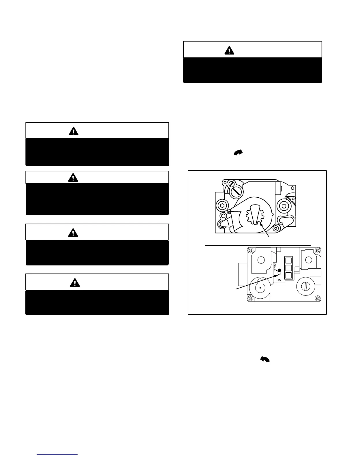
Procedure for checking and adjusting manifold pressure for proper gas valve operation.
Instructions for measuring the flame signal using a voltmeter and transducer.
Guide for selecting blower speeds on leadless motor models.
Recommendations for inspecting, cleaning, or replacing air filters.
Detailed steps for disassembling and cleaning the heat exchanger and burners.
Instructions for cleaning the burner assembly, including cover removal and manifold access.
Guidance on checking and cleaning the supply air blower motor and housing.
Diagrams showing typical field wiring and thermostat connections for G26 units.
Flowchart detailing the normal heating sequence of operation for the SureLight control.
Flowchart outlining abnormal heating mode sequences and potential issues.
Flowchart detailing the normal cooling sequence of operation for the SureLight control.
Step-by-step description of the heating sequence and blower operation.
Troubleshooting steps for unit failure to operate in cooling, heating, or continuous fan modes.
Troubleshooting steps when the combustion air blower does not start during heating.
Troubleshooting steps for ignition failure with combustion air blower energized.
Steps for diagnosing premature unit shutdown after burners light.
Procedure for addressing rough burner ignition and flame failure issues.
Diagnosing low flame sense signals and indoor blower operation failures.
Flowchart for troubleshooting the BCC2 blower control on -1 and -2 models.
Troubleshooting steps when spark is present but pilot fails to ignite.
Procedure for diagnosing and resolving issues where no spark is generated.
Steps for troubleshooting when the pilot lights but the main valve remains off.