Page 49
2
3
5
6
4
1
7 8
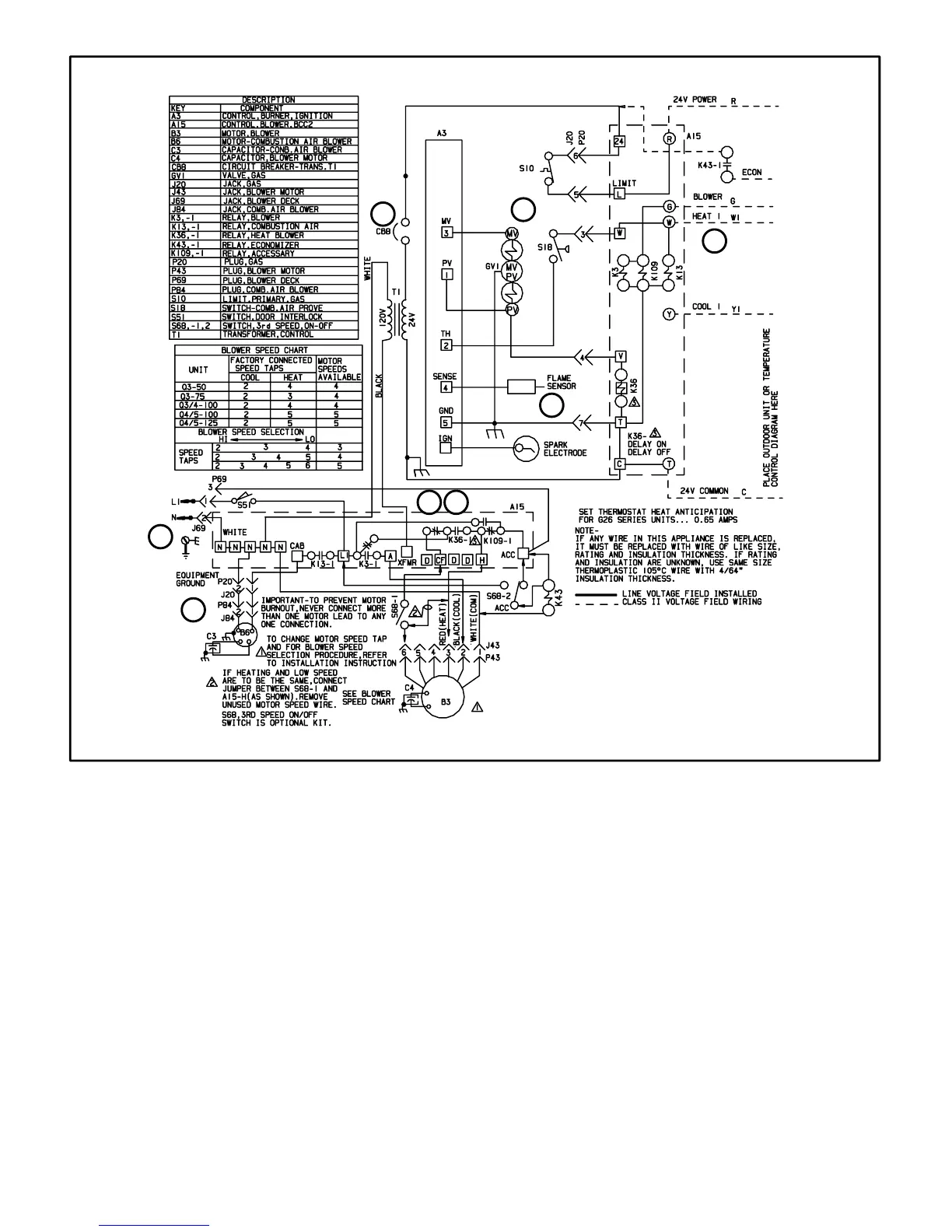
E− G26 −1 and −2 Models
1- When disconnect is closed, 120V is routed through
door interlock switch (S51) to feed the line voltage
side of the blower control (A3) and transformer T1 pri-
mary. Door interlock switch must be closed for A3 and
T1 to receive voltage.
2- T1 supplies 24VAC to terminal 24VAC" on A3. In turn,
terminal R" of A3 supplies 24VAC to terminal RC" of
the indoor thermostat (not shown).
3- When there is a call for heat, W1 of the thermostat en-
ergizes W of the furnace control with 24VAC.
4- CAB of the blower control energizes the combustion
air blower (B6). When the combustion air blower nears
full speed, combustion air prove switch (S18) closes.
5- When S18 closes, assuming primary limit (S10) is
closed, the ignition control opens the pilot valve and
begins spark.
6- When flame is sensed, spark stops and main valve
opens to light main burners.
7- After 45 seconds, blower control (A3) energizes the in-
door blower.
8- When heat demand is satisfied, W1 of the thermostat
de-energizes W of the furnace control and the furnace
control immediately de-energizes the gas valve. The
combustion air blower immediately stops. Also, the in-
door blower runs for a designated period (90−330 sec-
onds) as set by jumper on blower control.
 Loading...