Page 20
TABLE 13
VSP FACTORY SETTINGS FOR G32V−4 UNITS
MODEL
NUMBER
DELAY COOL ADJUST HEAT
G32V3−75 4 4 NORM 3
G32V5−100 4 4 NORM 2
G32V5−125 4 4 " 4
NOTE − In Harmony II zoning applications in the heating mode, the
highest cooling speed selected is the highest blower speed ob-
tainable. Also, the fan−only speed is used when the primary limit
has been tripped. In non−zoning applications, refer to the section
on the VSP3−1 control.
ADJUST
The ADJUST pins allow the motor to run at normal speed or
approximately 15% lower than normal speed. Blower
tables and the front of this manualgive two rows (NORMAL
and −) with their respective CFM volumes. The + adjust-
ment setting is not operable. Notice that the normal adjust-
ment setting for heat speed position #3 is 2030 CFM (955
L/s) in table 4. After the adjustment setting has been deter-
mined, choose the remainder speed jumper settings from
those in the table.
The TEST pin is available to bypass the VSP3−1 control and
run the motor at approximately 70% to test that the motor is
operational. This is beneficial primarily in troubleshooting. G
must be energized for motor to run.
HTG. BLOWER
For G32V−4 units only, place the HTG. BLOWER jumper
across the second and third pins (position #2).
NOTE − In Harmony II zoning applications, HTG. BLOWER
jumper must be in position #2.
HEAT
The HEAT jumper is used to set the blower speed to obtain
the required CFM as outlined in HEAT SPEED section of
tables 3 and 4.
The HEAT jumper selections are activated with a call for
first−stage heating (W1) and second−stage heating (W2).
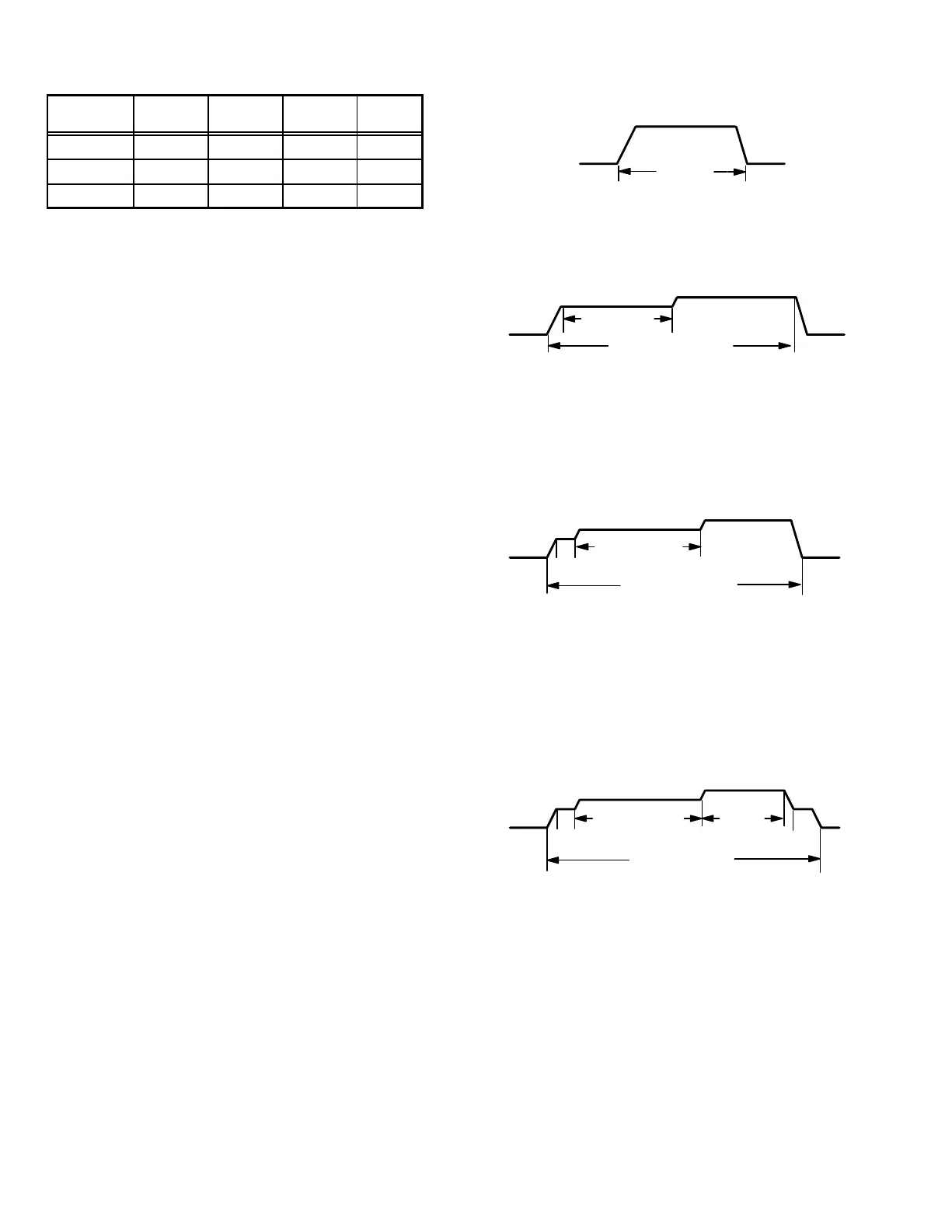
DELAY
The DELAY jumper is used to set the specific motor fan
mode of operation during cooling. Depending on the ap-
plication, one of four fan options may be chosen by moving
the jumper to the appropriate set of pins.
Options 1, 2, 3, or 4 will have an increased dehumidification
effect on the system. Option 1 will have the least effect and
option 4 will have the greatest effect.
#1 PIN JUMPERED
A − Motor runs at 100% until demand is satisfied.
B − Once demand is met, motor ramps down to off.
OFFOFF
A B
100% CFM
COOLING
DEMAND
#2 PIN JUMPERED
A − Motor runs at 82% for approximately 7−1/2 minutes.
B − If demand has not been satisfied after 7−1/2 minutes,
the motor runs at 100% until demand is satisfied.
C − Once demand is met, motor ramps down to off.
OFF
OFF
A
B
C
82%CFM
100% CFM
COOLING DEMAND
7 1/2 MIN
#3 PIN JUMPERED
A − Motor runs at 50% for 1/2 minute.
B − Motor then runs at 82% for approximately 7−1/2 min-
utes.
C − If demand has not been satisfied after 7−1/2 minutes,
motor runs at 100% until demand is satisfied.
D − Once demand is met, motor ramps down to off.
A
B
OFF
OFF
C D
1/2 MIN
50% CFM
7 1/2 MIN
82% CFM
100% CFM
COOLING DEMAND
#4 PIN JUMPERED
A − Motor runs at 50% for 1/2 minute.
B − Motor then runs at 82% for approximately 7−1/2 min-
utes.
C − If demand has not been satisfied after 7−1/2 minutes,
motor runs at 100% until demand is satisfied.
D − Once demand is met, motor runs at 50% for 1/2 min-
ute.
E − Motor ramps down to off.
A
B
OFF
OFF
C D
E
1/2 MIN
50% CFM
COOLING DEMAND
7 1/2 MIN
82% CFM
100%
CFM
1/2 MIN
50% CFM
COOL
The cool jumper is used to set the blower speed to obtain
the required CFM as outlined in tables 3 and 4.
VSP Operation
Table 14 and 15 outline the operation of the variable speed
motor in relation to specific modes of operation. Some infor-
mation has been repeated from the previous section to pro-
vide an example. Refer to each diagnostic LED or jumper
settings section for more information.
 Loading...


