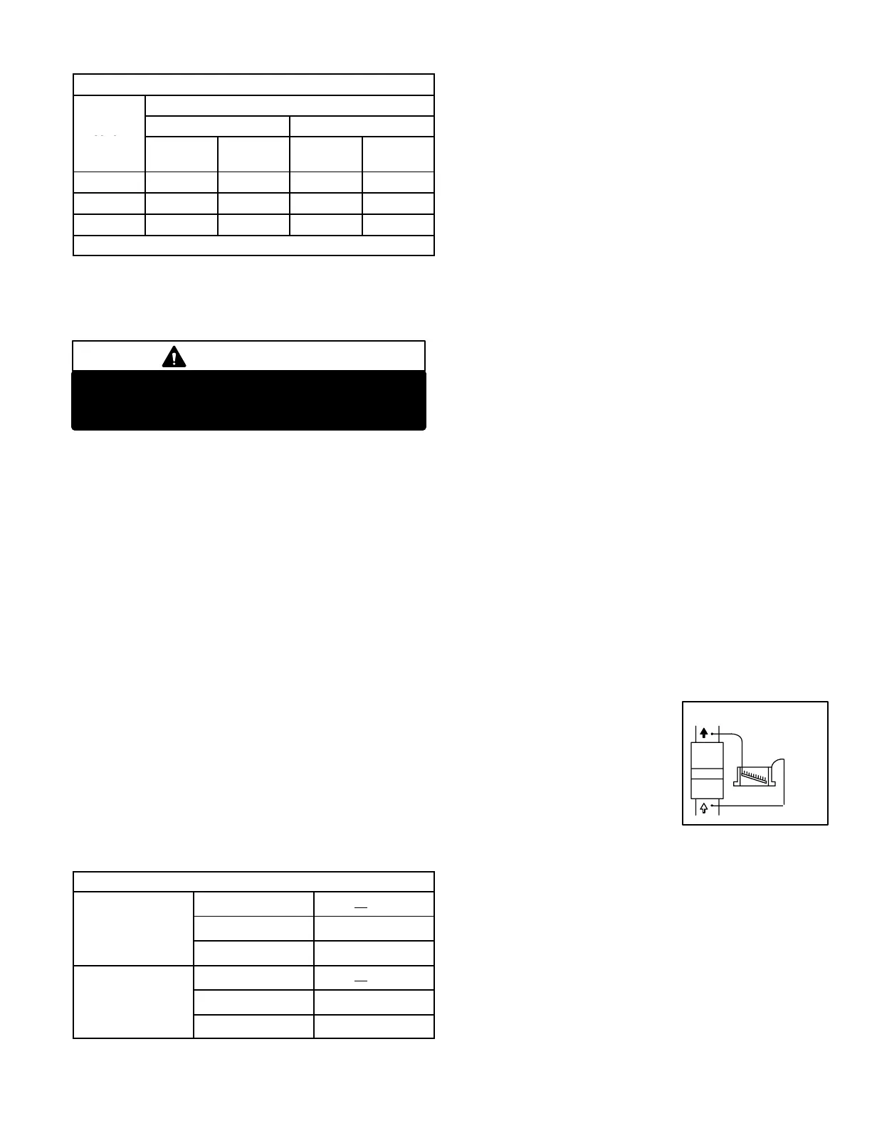
FIGURE 53
STATIC PRESSURE
TEST
MANOMETER
G32V UNIT
Page 49
TABLE 33
GAS METER CLOCKING CHART
Seconds for One Revolution
G32V
Natural LP
Unit
1 cu ft
Dial
2 cu ft
Dial
1 cu ft
Dial
2 cu ft
DIAL
−75 48 96 120 240
−100 36 72 90 180
−125 29 58 72 144
Natural−1000 btu/cu ft LP−2500 btu/cu ft
H−High Altitude Derate
See specifications section in this manual for manifold pres-
sure settings for installations at altitudes from 0 to 7500ft. (0
to 2286m).
IMPORTANT
For safety, shut unit off and remove manometer as
soon as an accurate reading has been obtained.
Take care to replace pressure tap plug.
I−Flame Signal
A microamp DC meter is needed to check the flame signal on
the SureLight control. Use a flame signal transducer (part
number 78H5401) available from Lennox to measure the
flame signal, if meter used will not read microamp signal.
Flame (microamp) signal is an electrical current which
passes from the ignition control through the sensor elec-
trode during unit operation. Current passes from the sensor
through the flame to ground to complete a safety circuit.
To Measure Flame Signal:
1 − Set the volt meter to the DC voltage scale. Insert trans-
ducer into the VDC and common inputs. Observe cor-
rect polarities. Failure to do so results in negative (−)
values.
2 − Turn off supply voltage to control.
3 − Disconnect flame sensor lead from terminal of ignition
control.
4 − Connect (+) lead of transducer to ignition control sen-
sor connection.
5 − Connect (−) lead of the transducer to sensor wire.
6 − Turn supply voltage on and close thermostat contacts
to cycle system.
7 − When unit lights, read voltage on meter display. Re-
member 1 DC volt = 1 DC microamp.
TABLE 34
FLAME SIGNAL MICROAMPS
Boards
Normal u0.23
46M99
Low 0.17 to 0.22
18M99
49M59
Drop Out 0.16
Boards
Normal u0.61
24L85
Low 0.21 to 0.60
56L83
97L48
Drop Out 0.20
V−TYPICAL OPERATING CHARACTERISTICS
A−Blower Operation and Adjustment
NOTE− The following is a generalized procedure and
does not apply to all thermostat controls.
1 − Blower operation is dependent on thermostat control
system.
2 − Generally, blower operation is set at thermostat sub-
base fan switch. With fan switch in ON position, blower
operates continuously. With fan switch in AUTO position,
blower cycles with demand or runs continuously while
heating or cooling circuit cycles.
3 − In all cases, blower and entire unit will be off when the
system switch is in OFF position.
B−Temperature Rise
Temperature rise for G32V units depends on unit input,
blower speed, blower horsepower and static pressure as
marked on the unit rating plate. The blower speed must be
set for unit operation within the range of AIR TEMP. RISE
°F" listed on the unit rating plate.
To Measure Temperature Rise:
1 − Place plenum thermometers in the supply and return air
plenums. Locate supply air thermometer in the first hori-
zontal run of the plenum where it will not pick up radiant
heat from the heat exchanger.
2 − Set thermostat to highest setting.
3 − After plenum thermometers have reached their highest
and steadiest readings, subtract the two readings. The
difference should be in the range listed on the unit rat-
ing plate. If the temperature is too low, decrease blower
speed. If temperature is too high, first check the firing
rate. Provided the firing rate is acceptable, increase
blower speed to reduce temperature. To change blow-
er speed taps see the Blower Speed Taps section in this
manual.
C−External Static Pressure
1 − Measure tap locations as shown in figure 53.
2 − Punch a 1/4" diameter hole
in supply upstream of evapo-
rator and return air plenums.
Insert manometer hose flush
with inside edge of hole or in-
sulation. Seal around the
hose with permagum. Con-
nect the zero end of the ma-
nometer to the discharge (supply) side of the system.
On ducted systems, connect the other end of manome-
ter to the return duct as above. For systems with non−
ducted returns, leave the other end of the manometer
open to the atmosphere.
3 − With only the blower motor running and the evaporator
coil dry, observe the manometer reading. Adjust blower
motor speed to deliver the air desired according to the
job requirements.
4 − Pressure drop must not exceed 0.8" W.C.
5 − Seal around the hole when the check is complete.
 Loading...


