Page 4
BLOWER PERFORMANCE
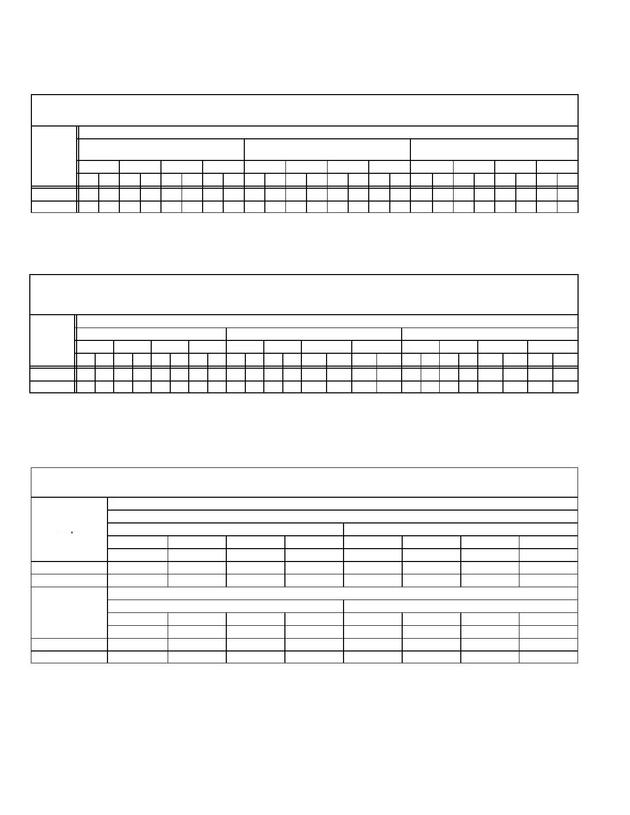
Table 1
G32V3−75−1 through −3 Units
0 THROUGH 0.80 IN. W.G. (0 THROUGH 200 PA) EXTERNAL STATIC PRESSURE
VSP2-1 Blower Control Low Speed 3
Factory Settings High Speed 4
Heat Speed 3
VSP2−1 Jumper Speed Positions
ADJUST"
Jumper
LOW" Speed
(Cool, Low Heat Or Continuous Fan)
HIGH" Speed (Cool) HEAT" Speed
Setting
1 2 3 4 1 2 3 4 1 2 3 4
cfm L/s cfm L/s cfm L/s cfm L/s cfm L/s cfm L/s cfm L/s cfm L/s cfm L/s cfm L/s cfm L/s cfm L/s
NORM 880 415 930 440 980 465 1040 490 1060 500 1105 520 1260 595 1330 630 1075 510 1150 545 1270 600 1350 635
− 15% 775 365 810 380 850 400 910 430 930 440 970 460 1070 505 1130 535 930 440 990 465 1080 510 1140 540
NOTE The effect of static pressure and filter resistance is included in the air volumes listed.
Table 2
G32V5−100/125−1 through −3 Units
0 THROUGH 0.80 IN. W.G. (0 THROUGH 200 PA) EXTERNAL STATIC PRESSURE
VSP2-1 Blower Control G32V5−100 G32V5−125
Factory Settings Low Speed 2 Low Speed 3
High Speed 4 High Speed 4
Heat Speed 1 Heat Speed 2
VSP2 Jumper Speed Positions
ADJUST"
LOW" Speed (Cool Or Continuous Fan) HIGH" Speed (Cool) HEAT" Speed
Jumper
Settin
1 2 3 4 1 2 3 4 1 2 3 4
cfm L/s cfm L/s cfm L/s cfm L/s cfm L/s cfm L/s cfm L/s cfm L/s cfm L/s cfm L/s cfm L/s cfm L/s
NORM 1140 540 1250 590 1440 680 1550 730 1620 765 1820 860 2000 945 2100 990 1560 735 1720 810 2030 960 2150 1015
− 970 460 1060 500 1280 605 1320 625 1380 650 1550 730 1700 800 1780 840 1330 630 1460 690 1730 815 1830 865
NOTE The effect of static pressure and filter resistance is included in the air volumes listed.
G32V5−125 unit only − do not place jumper on tap 1 ("") for high speed or tap 2 ("NORM" or "") for low speed.
Table 3
G32V3−75−4 Units
0 THROUGH 0.80 IN. W.G. (0 THROUGH 200 PA) EXTERNAL STATIC PRESSURE
VSP3−1 Blower Control Factory Settings ADJUST − NORM
Heat Speed − 3
Cool Speed − 4
VSP Jumper Speed Positions
"
HEAT" Jumper
Jumper
Low Speed High Speed
Positions
1 2 3 4 1 2 3 4
cfm L/s cfm L/s cfm L/s cfm L/s cfm L/s cfm L/s cfm L/s cfm L/s
NORM (Normal) 880 415 930 440 980 465 1040 490 1075 510 1150 545 1270 600 1350 635
" (Minus) 15% 775 365 810 380 850 400 910 430 930 440 990 460 1080 510 1140 540
COOL" Jumper
ADJUST"
Low Speed High Speed
Jumper
Positions
1 2 3 4 1 2 3 4
cfm L/s cfm L/s cfm L/s cfm L/s cfm L/s cfm L/s cfm L/s cfm L/s
NORM (Normal) 880 415 930 440 980 465 1040 490 1060 500 1105 520 1260 600 1350 635
" (Minus) 15% 775 365 810 380 850 400 910 430 930 440 970 460 1080 510 1140 540
15% lower motor speed than NORM jumper setting.
NOTE − The effect of static pressure and filter resistance is included in air volumes shown.
NOTE − Continuous Fan only speed is approximately 800 cfm (380 L/s) − non adjustable.
NOTE − Lennox Harmony II zone control applications − MAX CFM is determined by COOL jumper placement with a minimum of approximately 850 cfm (400 L/s) for all positions.
 Loading...


