Page 83
3− Variable Speed Blower Motor
To check−out the VSM blower and the blower control board,
begin with the ICM2 motorand follow the check−out procedure
as outlined. The ICM2 consist of a control module and motor.
The control module can be replaced separately from the motor
if necessary. However, if the motor fails the motor/module as-
sembly must be replaced. To verify proper operation of the
blower control board, check the board as outlined in the trou-
bleshooting flowcharts on the previous page.
1− Disconnect power to unit.
2− Disconnect plug J46 from P46 located on the
blower control board.
3− Connect voltage source as shown above.
4− Turn on power to unit. Blower should operate
at low speed.
LOW SPEED CHECK−OUT
Unit transformer T1 with a maximum AC 30 volts
may be used in lieu of a battery. If transformer T1
is used, double check all wiring connections be-
fore placing unit back in operation.
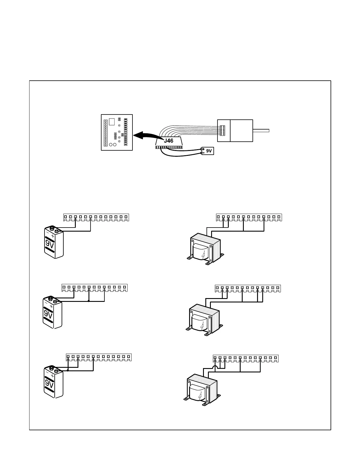
CHECK−OUT PROCEDURE USING BATTERY
6− Disconnect power to unit.
7− Connect voltage source as shown above.
8− Turn on power to unit. Blower should operate
at high speed.
HIGH SPEED CHECK−OUT
9− Disconnect power to unit.
10−Connect voltage source as shown above.
11−Turn on power to unit. Blower should operate
at heating speed.
HEATING SPEED CHECK−OUT
12345678910111213
12345678910111213
12345678910111213
J46
J46
J46
CHECK−OUT PROCEDURE USING 24V SOURCE
LOW SPEED CHECK−OUT
12345678910111213
J46
R
C
HIGH SPEED CHECK−OUT
12345678910111213
J46
R
C
HEATING SPEED CHECK−OUT
12345678910111213
J46
R
C
1− Disconnect power to unit.
2− Disconnect plug J46 from P46 located on the
blower control board.
3− Disconnect C and R from control board.
4− Connect voltage source as shown above.
5− Turn on power to unit. Blower should operate
at low speed.
6− Disconnect power to unit.
7− Connect voltage source as shown above.
8− Turn on power to unit. Blower should operate
at high speed.
9− Disconnect power to unit.
10− Connect voltage source as shown above.
11− Turn on power to unit. Blower should operate
at heating speed.
A kit is available from the Lennox parts center to use in testing the variable speed motor. The kit 70J11 includes a test plug
harness to facilitate ICM−2 check−out. Follow testing procedures outlined in the instructions provided with the kit.
The testing procedures are different than those listed above.
An ordinary 9 volt battery with maximum DC
20volts is recommended. A 9 volt battery will
last for about one day of normal operation.
120V to the motor must not be interrupted. All connections for check out will be from the volt-
age source below (battery or 24V) to plug J46, after disconnecting from blower control board.
J46
1
13
1
13
ICM−2 WITH VSP2