Page 18
7.VSP3−1 Blower Control Board (A24)
G32V−4 Units
G32V−4 units are equipped with a variable speed motor that
is capable of maintaining a specified CFM throughout the
external static range. The unit uses the VSP3−1 variable
speed control board, located in the blower compartment,
which controls the blower speed and provides diagnostic
LEDs. The control has both a non−adjustable, factory preset
ON" fan timing delay and an adjustable OFF" fan timing delay
(see figure 13).
The VSP3−1 also senses limit trip condition and turns on the
blower. The G32V limit switch is located in the middle of the
vestibule wall. When excess heat is sensed in the heat ex-
changer, the limit switch will open and interrupt the current
to the gas valve, while at the same time the VSP3−1 energizes
the blower on heating speed. The limit automatically resets
when the unit temperature returns to normal and the blower is
de−energized.
Diagnostic LEDs located on the VSP3−1 control board are pro-
vided to aid in identifying the unit’s mode of operation. Certain
scenarios will arise depending on the jumper positions. Refer
to figure 14 for identification.
IMPORTANT
24 VAC half wave rectified (DC pulse), when mea-
sured with a meter, may appear as a lower or
higher voltage depending on the make of the me-
ter. Rather than attempting to measure the output
voltage of A24, see G32V BLOWER & VSP3
BLOWER CONTROL BOARD TROUBLESHOOT-
ING FLOW CHART in the TROUBLESHOOTING
section of this manual.
JP2
DELAY COOL ADJUST HEAT
CFM
HI/LOW
ON/OFF
HEAT
HTG.
BLOWER
12
DS2
DS3
DS1
DS4
1
2
3
4
1
2
3
4
1
2
3
4
TEST
−
+
NORM
210
150
90
270
JP1
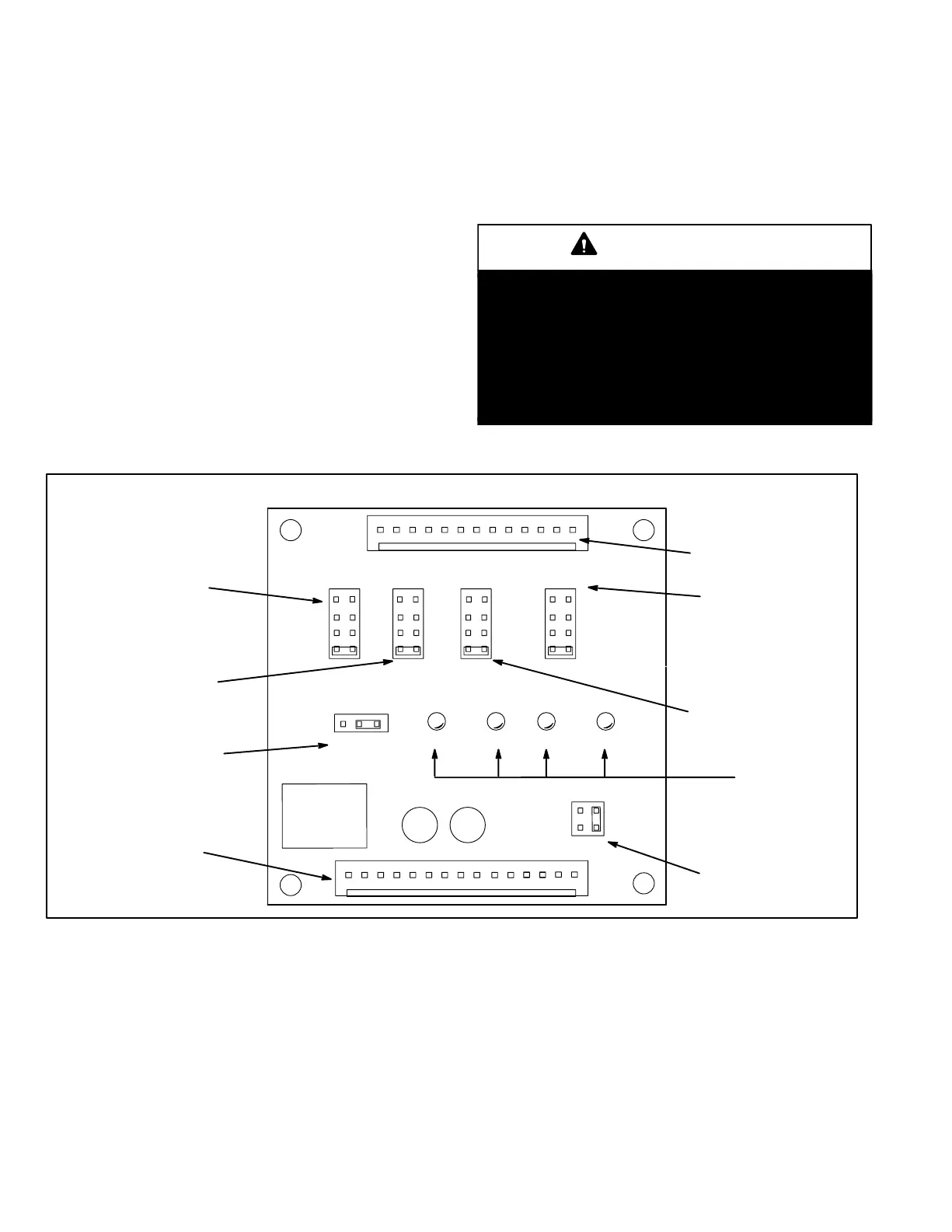
VSP3−1 VARIABLE SPEED CONTROL BOARD SELECTIONS
DIAGNOSTIC
DS LEDS
FAN OFF"
TIMING PINS
JP46
13 PIN PLUG
(BOARD TO MOTOR)
HEATING STAGE
JUMPER SELECTOR PINS
JP73
15 PIN PLUG
(BOARD TO VARIOUS
POINTS IN FURNACE)
DELAY PROFILE
SELECTOR PINS
(COOLING ONLY)
COOL SPEED
SELECTOR PINS
(COOLING, HEATING and
CONTINUOUS FAN)
HEATING SPEED
SELECTOR PINS
OPERATIONAL
SELECTOR PINS
(Affects both heating
and cooling modes)
1
1
See table 13 for VSP3−1
factory settings
FIGURE 14
 Loading...


